Electrical connections – IDEC DATAVS1 Series User Manual
Page 7
Instruction Manual
SVS1 Series
2
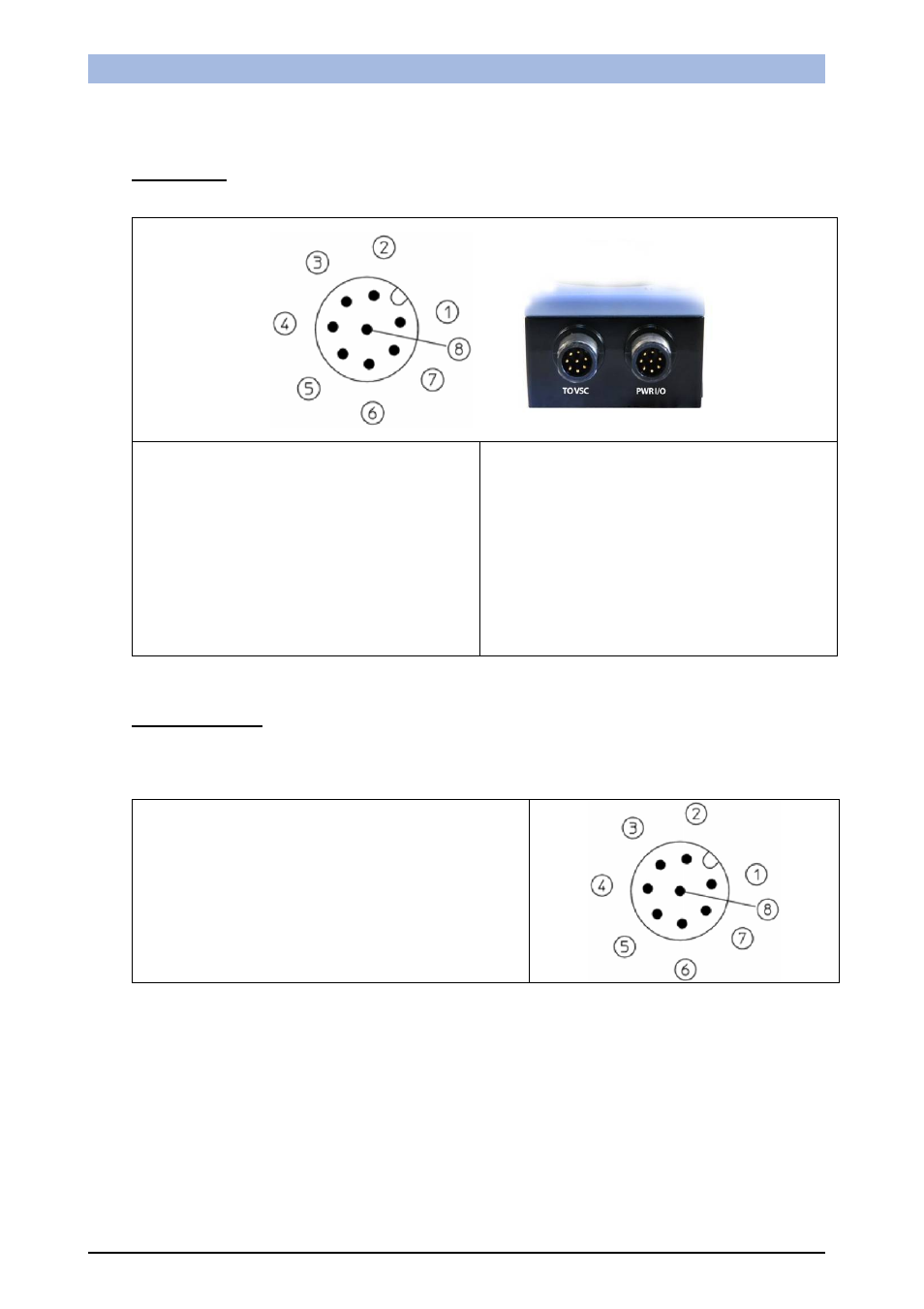
2. ELECTRICAL CONNECTIONS
SVS1 sensor
M12 8 poles
(VSC connection)
pin 1: ethernet TX+
pin 2: ethernet RX+
pin 3: ethernet RX-
pin 4: not used
pin 5: 24 Vdc
pin 6: not used
pin 7: ethernet TX-
pin 8: GROUND
M12 8 poles
(power and I/O)
pin 1: white : digital input 1
pin 2: brown : 24 Vdc
pin 3: green : STROBE for external illuminator
pin 4: yellow : output 1
pin 5: grey : output 2
pin 6: pink : output 3
pin 7: blue : GROUND
pin 8: red : external trigger
VSC Configurator
M12 8-pole Ethernet: (SVS1 connection)
pin 1: ethernet TX+
pin 2: ethernet RX+
pin 3: ethernet RX-
pin 4: not used
pin 5: 24 Vdc
pin 6: not used
pin 7: ethernet TX-
pin 8: GROUND