IDEC DATAVS1 Series User Manual
Page 29
Instruction Manual
SVS1 Series
24
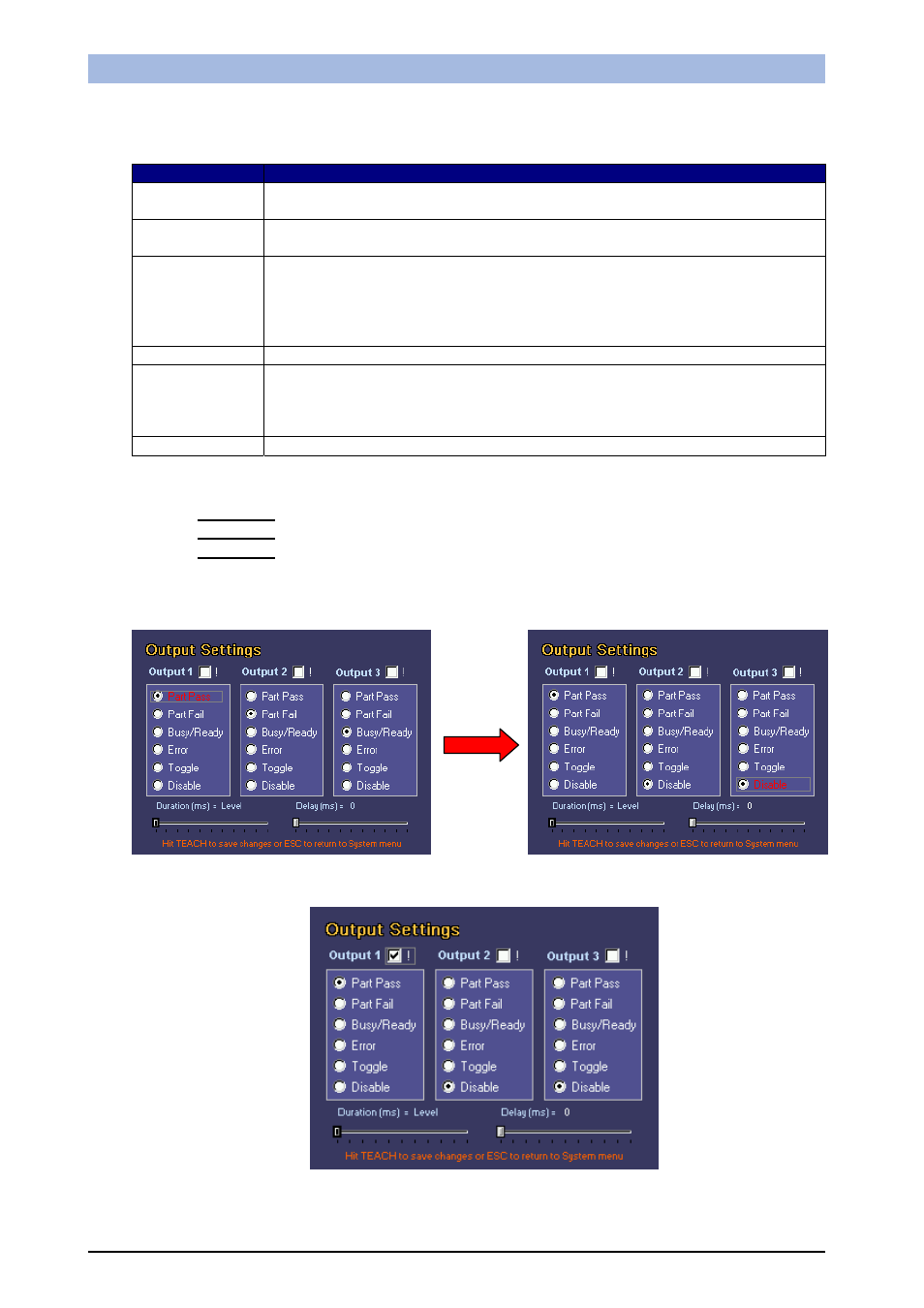
As seen in the image below, it is possible to assign a different behaviour to each output.
Option
Behaviour
Part pass
The output is enabled when the inspection gives a positive result. If a failure
occurs it remains low.
Part fail
The output is enabled if a failure occurs. If the inspection gives a positive
result, it remains disabled.
Busy-Ready
The output takes on value 1 (Busy) for the entire time the sensor takes to
acquire and process the image. The output takes on value 0 (Ready) when the
sensor is ready to acquire a new image. If the image is acquired under the
control of an external signal (hardware trigger), the output will take on value 1
on receiving the signal.
Error
This indicates an error on the sensor.
Toggle
The output will indicate alternately the logic values 1 and 0 each time it
acquires and processes an image. In this configuration there is no relation
between the value indicated on the output and the result of the processed
image.
Disable
The output is disabled
By default the three outputs have the following settings:
•
OUTPUT 1
: Part pass
•
OUTPUT 2
: Part fail
•
OUTPUT 3
: Busy-Ready
To select the required behaviour, use the ARROW buttons to select the option and press the SET
button.
Each output can also be configured in negative logic. To invert the function logic, use the ARROW
buttons to select the option at the top with an exclamation mark, and press the SET button.