Inspection configuration using vsc, Introduction, Vsc user interface – IDEC DATAVS1 Series User Manual
Page 17: Button
Instruction Manual
SVS1 Series
12
5. INSPECTION CONFIGURATION USING VSC
5.1.
Introduction
The configuration of the SVS1 vision sensor can only be performed using the VSC unit.
This chapter provides the basic procedures to follow in order to programme the sensor settings
correctly. Chapters 6 and 7 provide further details on the various configuration options and a more
complete panorama on the SVS1 functions.
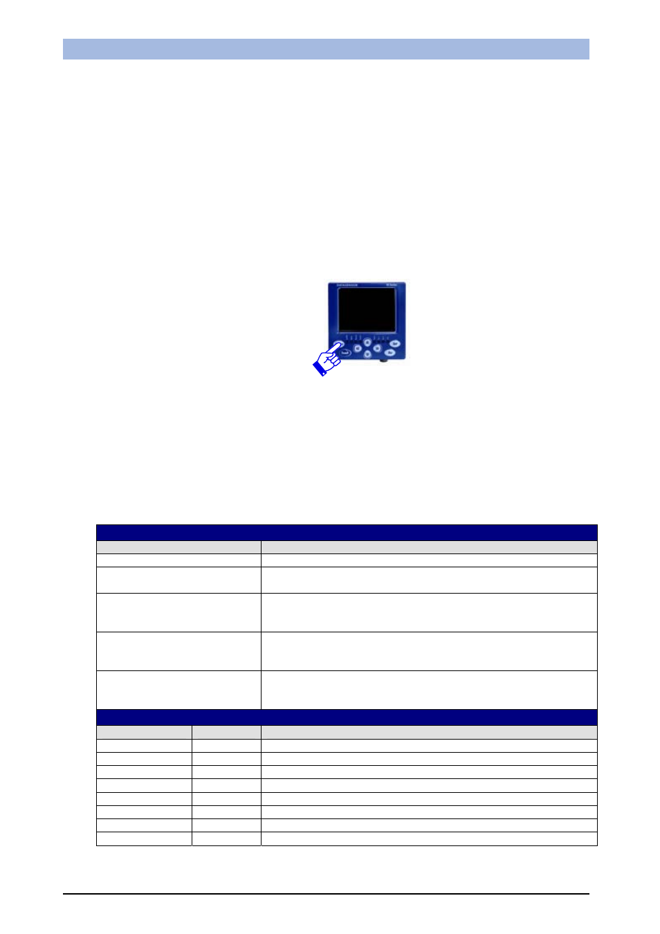
To simplify the instructions described in this manual the pressing of the buttons on the configurator
user interface will be indicated using the following diagram:
Example: Press the "Status" button
5.2.
VSC user interface
The chart below provides a general overview of the user interface on the VSC configurator. Please
note however that the functions of the buttons vary according to the operating mode selected by the
user. Please consult the next chapters for further details on how the system reacts to the pressing of
the buttons.
BUTTON
ID button
Main functions
Status
Go to the next configuration status
Teach
Saving of settings
Acquire a new reference image
Set
Confirms selected option
Confirms setting value
Changes monitor mode
Esc
Exit without saving
Back to previous screen
Back to the previous configuration step
Arrows
Changes selected option
Movement/resizing of the ROI
Changes the parameters
LED
LED ID
Colour
Meaning
Power
Green
VSC Configurator correctly powered up
Out 1
Orange
Digital output 1 active
OUT 2
Orange
Digital output 2 active
Link
Green
VSC Configurator correctly connected to the sensor
Set/Net
Green
Current status: Setup
Adjust
Green
Current status: Adjust
Monitor
Green
Current status: Monitor
System
Green
Current status: System