Setup example - fuel injector, Setup example - fuel injector volts & amps, Setup example - fuel pump waveform – GxT Ferret 92 Color Labscope User Manual
Page 9
9
www.gxtauto.com
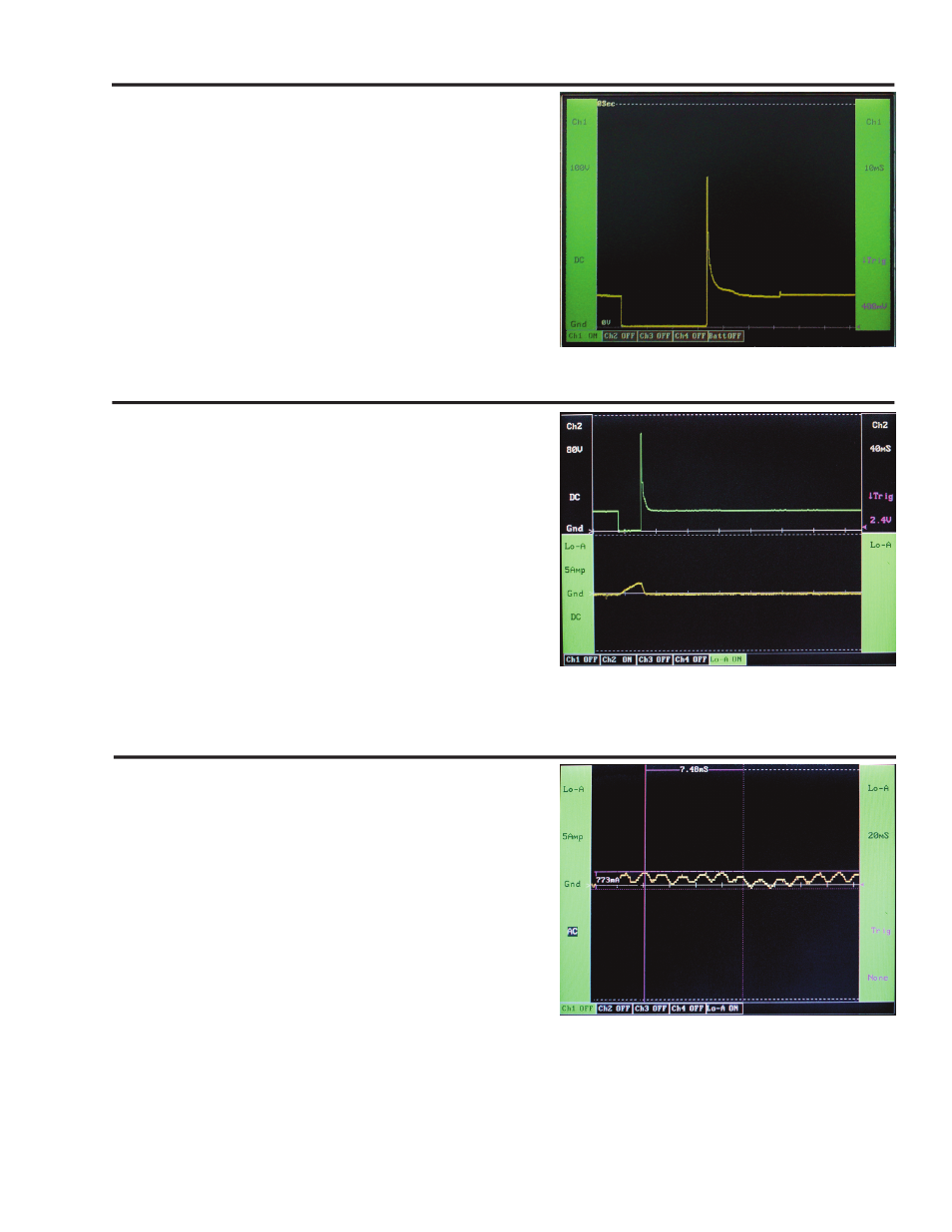
Setup Example - Fuel Injector
In this example Channel 1 is used to connect directly to a fuel
injector. Make sure both the ground and sense leads for the
channel have a good signal.
Setup Characteristics:
Channel 1
Voltage ......................DC Coupled, Ground at the Bottom, 100V
Time Base .......................................................................... 12 ms
Trigger .......................................Channel 1, down slope, 400 mV
You can use the hold mode and cursors to accurately measure
the on time and peak voltage. Once you have this set up for one
injector, it is very easy to move from injector to injector to measure
their performance.
Setup Example - Fuel Injector Volts & Amps
In this example Channel 2 is used to connect directly to a fuel
injector, and the auxiliary Lo Amps probe is used to measure the
current ramp. Make sure both the ground and sense leads for
channel 2 have a good signal.
Setup Characteristics:
Channel 2
Voltage ......................DC Coupled, Ground at the Bottom, 100V
Time Base .......................................................................... 12 ms
Trigger ............................................Channel 2, down slope, 2.4V
Lo Amps Auxiliary Channel
Amperage ..................................................DC Coupled, 5 Amps
This setup allows you to look at the voltage and amperage
waveform at the same time.
Setup Example - Fuel Pump Waveform
In this example only the low amps probe is used. It is connected
to the wire that supplies battery power to the fuel pump.
Setup Characteristics:
Lo Amps Auxiliary Channel
Amperage .......................................................... AC Coupled, 5A
Time Base .......................................................................... 20 ms
Trigger ......................................................................... No Trigger
The fuel pump was turned on and the following waveform was
displayed. The hold mode was engaged and the cursors were
used to measure the amount of AC ripple and the total time of
one revolution of the pump.