GxT Ferret 92 Color Labscope User Manual
Page 20
20
www.gxtauto.com
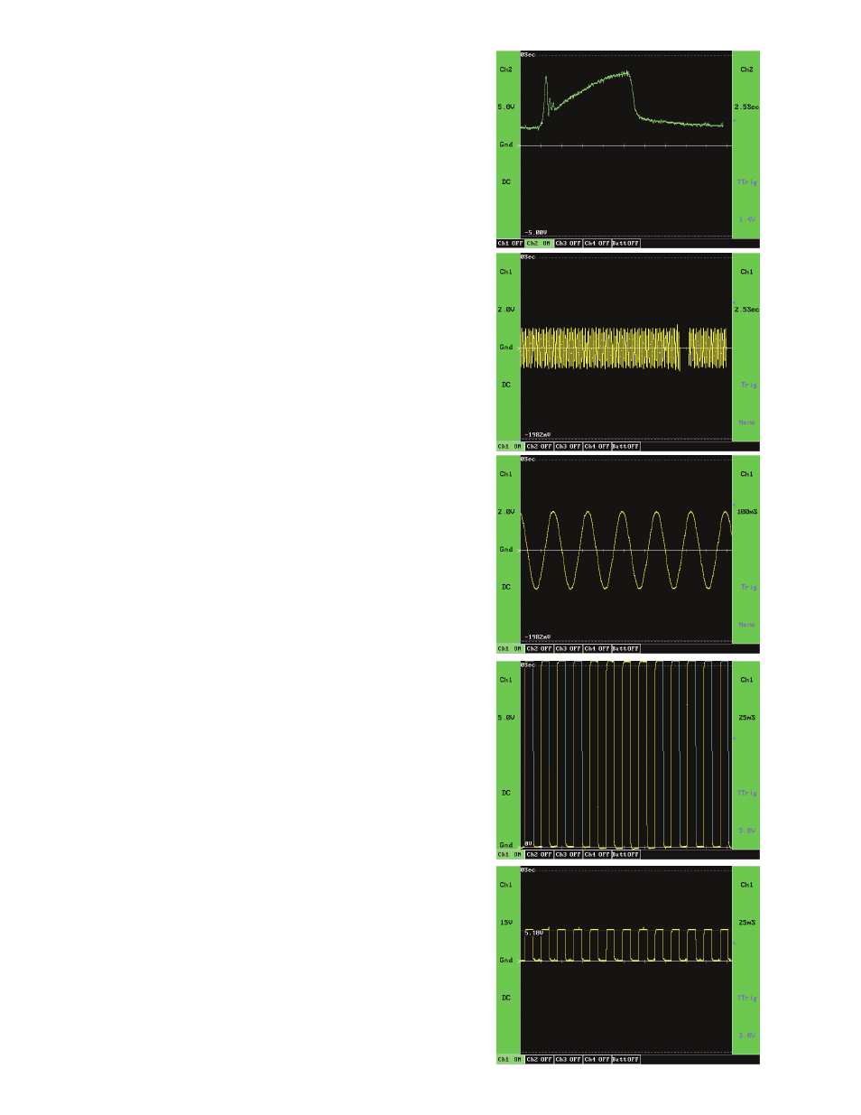
Mass Air Flow Sensor:
This MAF Sensor (Fig. 11) is also a low speed analog signal marked by
mixed speed voltage transitions. Although the initial voltage transition
is fairly fast it is still viewable in real time.
Because this signal is a lot like the TPS used in the previous example
we have used the same settings with the exception of Trigger Level.
Normally the same Trigger level could have been used, but this capture
was from a cold engine, so idle voltage was higher than the normal
of about .6 volts.
AC Voltage:
This AC Voltage signal (Fig. 12) is a high speed analog signal, marked
by fast voltage transitions. As you can see, it is not viewable in real
time. We need to adjust the Time base to view this signal.
With this setup (Fig. 13) we can properly view this AC Sine Wave.
Voltage Scale is set at 2.0 volts because we expected less than that.
DC Coupling was used, but the trace would have been drawn the same
with AC coupling. Ground in the middle as it should be when viewing
an AC signal. Time base is set to 100mS and no trigger was set so
trigger level does not apply. We could have used either a positive or
negative slope trigger and set trigger level at any level within the range
of the trace. This would have kept the trace from scrolling across the
screen.
Square Wave:
This capture (Fig. 14) is a high speed Digital signal marked by very fast
voltage transitions and is not viewable in real time. As you can see,
a Voltage Scale of 5 volts is too low. The Ferret 92 scope will show a
light blue trace when the signal ranges off of the display.
Fig. 15 shows the same signal as Fig. 14, but with the Voltage Scale
adjusted. The cursor voltage shows why it was over ranged in the
previous capture. Here Voltage Scale is set at 15 volts. It could have
been set lower, but we see everything we need to at this setting. DC
Coupling and ground in the middle work well here. A very short Time
base of 20mS was used and allows us to see eight cycles. A little math
and we know that the frequency of this signal is a little over 400Hz.
Positive slope Trigger, although negative slope would work just as well,
and a Trigger Level very close to the middle of the voltage transition.
This is a good place to set trigger level on most digital signals. If trigger
level were set too high or low and circuitry problems kept voltage from
achieving the set level the scope wouldn’t trigger so we wouldn’t see
the bad events, and wouldn’t know if there was a problem.