Analyzing waveforms – GxT Ferret 92 Color Labscope User Manual
Page 22
22
www.gxtauto.com
Analyzing Waveforms
You now know the basic settings and have seen them used in examples.
In the following pages we will look at a couple of captures and what
they tell us about the events.
TPS Sweep Test:
Fig. 9 is a TPS sweep test. This test is used to look for glitches
(abnormalities) that may be present at any level of throttle opening.
These glitches may appear in the trace as upward lines (spikes),
downward lines (dropouts) or erratic areas (areas where voltage either
doesn’t change with throttle position change or the change doesn’t
follow a normal trend). We may also fi nd a fl at line throughout the
sweep at or near either 0 volts (open circuit or short to ground), 5
volts (shorted to VREF) or between 5 and 15 volts (usually shorted to
system voltage).
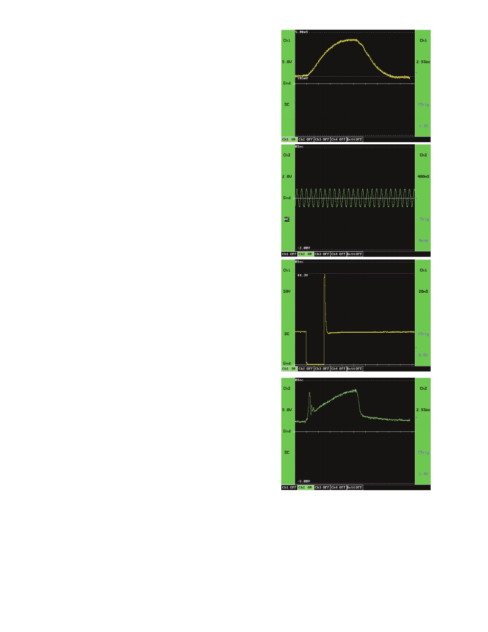
The capture in Figure 1 shows a normal sweep. Voltage is about .7
volts with the throttle at rest and about 4.3 volts wide open with smooth
transitions and no spikes or dropouts.
Fig. 17 is a typical port fuel injector at idle. As previously stated, we are
connected to the control, or ground side, of the injector and a good
ground. The power side of the injector has B+ to it whenever the key is
on. Until the injector is pulsed we will also have B+ at our connection
on the control side unless the injector winding is open circuit, as you
can see by looking at the horizontal part of the trace on either side of
the event.
When the driver in the computer completes the circuit on the control
side, we see the signal pulled to ground (fi rst vertical line). As the falling
voltage passes the trigger level the scope begins to draw the trace.
The voltage is held at ground for about 3 mS. This is the injector on
time, or pulse width.
The second vertical line shows the driver opening the circuit, which
causes the magnetic fi eld in the injector winding to collapse. This
produces an inductive kick, or voltage spike, of about 44.3 volts (varies
with application). If you look at the curved line as voltage returns to
system voltage you should see a small hump. This is the injector pintle
altering the magnetic fi eld as it slams shut.
The capture in Figure 2 shows a good injector and good circuitry. The
fact that the control side can pull the voltage to ground and hold it
there proves the driver and control side circuitry. The inductive kick
shows the integrity of the winding and power side circuit. The pintle
hump verifi es that the injector is opening. For further confi rmation this
injector could be compared to others on the same vehicle
MAF 2 Second Snap Throttle Test:
Figure 11 is a voltage trace of a mass airfl ow (MAF) sensor when
the throttle was snapped open for about 1.5 seconds. The positive scope lead is connected to the signal wire
and the negative lead to signal return (signal ground). This is a hot wire type sensor that is used on most Ford
applications.
This MAF sensor operates in a 5 volt range, as do most sensors. Increases in airfl ow will be seen as increases
in voltage. Looking at this capture you can see that the voltage is 1.3 volts at cold idle and has a lot of hash in it.
The hash is airfl ow pulsation caused by manifold vacuum changes as intake valves open and close. The fi rst rapid
increase and then drop in voltage occurs when the throttle is snapped open and a surge of air is drawn into the
intake manifold. At idle the pressure was negative in the intake manifold and positive on the air intake side of the
throttle plate, so this surge is a result of the pressure equalizing when the throttle is opened wide. You can see