Basic waveforms – GxT Ferret 92 Color Labscope User Manual
Page 19
19
www.gxtauto.com
settings for each channel, but only the settings on the active, or highlighted channel will be used. You may move
the highlight to another channel by using the Channel Select key. The time base of the highlighted channel will then
apply to all channels. To activate the trigger on the highlighted channel press either Trigger key once the channel
is active.
Basic Waveforms
Coolant Temp. Sensor:
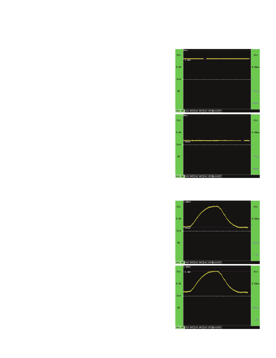
Fig. 7 is a low speed analog signal, marked by very slow voltage
transitions, and is viewable in real time. We used a cursor here to
measure the voltage level. As you can see, at 3.5 volts, we’re looking
at a coolant temperature of about 50* F.
Fig. 8 is the same CTS as Fig. 7 but, as you can see, the engine is
now at about 180*F as indicated by a voltage level of about .7 volts.
Let’s look at the settings and why these settings were used. Voltage
Scale 5 volts. Normal range for this signal is between about .4 and 4.6
volts. DC coupling is used because we want to see the voltage level.
Time Base is set at 5 seconds. Remember, we are viewing this signal
in real time, with a slight delay.
When a Time Base of 1 second or more is used on the Ferret 92 scope
it goes into what we call rolling mode. This means that the trace will
update by scrolling across the display. You’ll notice a break in the
trace. The old trace is scrolling off of the right side of the screen while
the updated trace is replacing it on the left side of the break. The time
base setting will tell you how long it takes for the display to complete
an upgrade, in this case it will take 5 seconds. We don’t need a trigger
for this type of signal, so the Trigger setting is None and trigger level
does not apply.
Throttle Position Sensor
This TPS (Fig. 9) is also a low speed analog signal. In this case we are
controlling the voltage transitions by opening and closing the throttle.
This signal is viewable in real time. We have set a voltage cursor at
closed throttle voltage, which is about .7 volts.
Fig. 10 is the same capture as Fig. 9, but the cursor is now at WOT, or
4.3 volts. Voltage Scale is set at 5 volts, just like it was for the CTS. We
used DC coupling so we can see voltage levels, and Ground Location
in the middle, because it allows plenty of vertical resolution.
A positive slope trigger was used because the event begins with
increasing voltage when we start to open the throttle. Trigger Level is
set at 1.1 volts. Because the scope stores the input it can display what
occurred before it actually triggers at 1.1 volts, so we see the voltage
transition from the beginning. By setting a trigger we are also telling
the scope that we want the trace to remain on the display unless the
trigger criteria is met again. If we opened the throttle again a trace of
the new event would replace this one.