Part names, Rear panel, English – Sanyo DSR-3016 User Manual
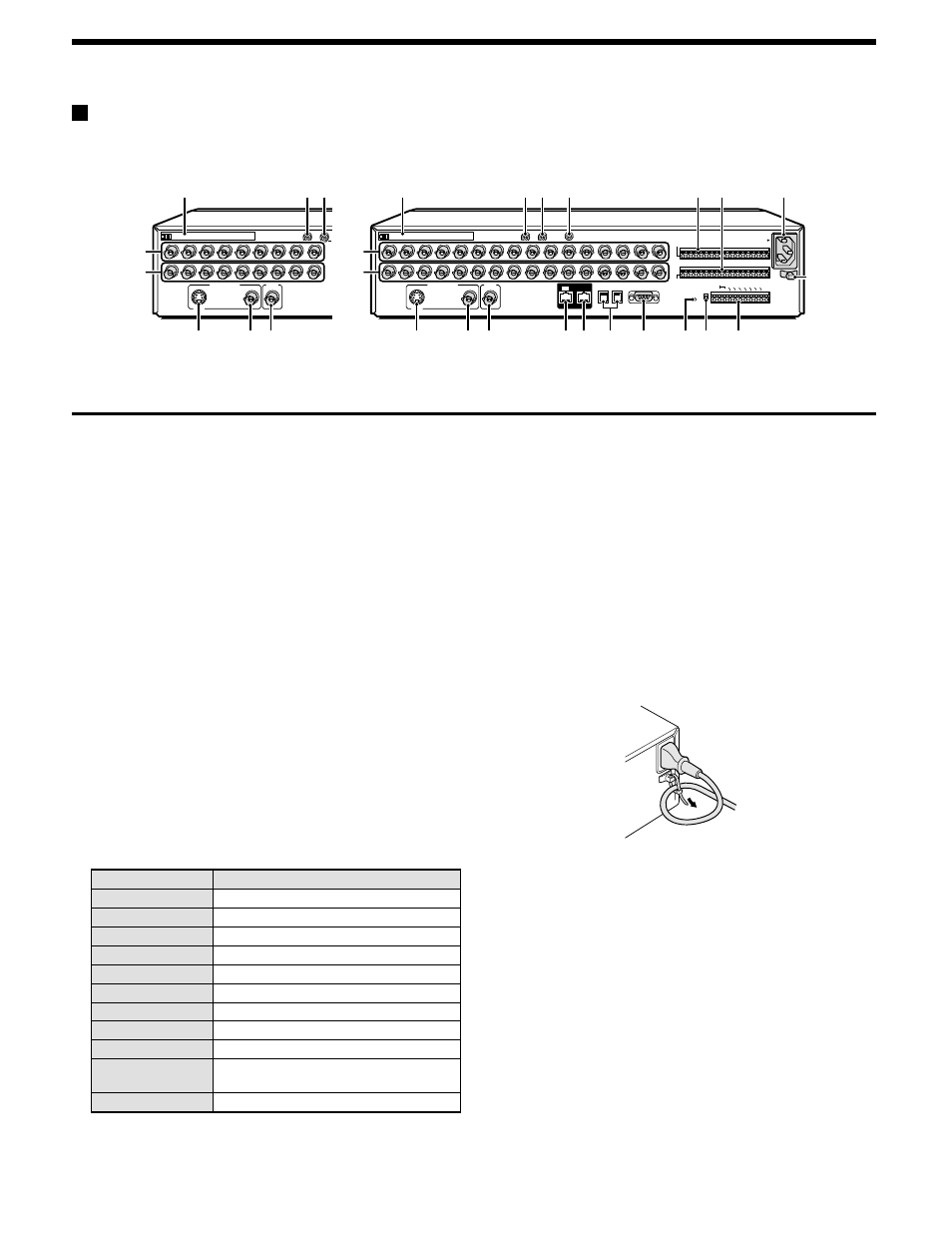
Page 8: Audio in terminal, Audio out terminal, Mic in terminal, Main monitor s-video output terminal, Main monitor output terminal, Mon2 output terminal, Digital in terminal
PART NAMES
Rear panel
1
PC card slot
Connect a network card or SCSI card (sold separately) here.
Note: The PC card slot is for 16-bit 5 V cards only.
Do not use 32-bit card bus types of card, as they may
damage the PC card slot of the digital video recorder.
2
AUDIO IN terminal
3
AUDIO OUT terminal
4
MIC IN terminal
5
VIDEO IN terminal
The DSR-3009 model has nine input terminals.
6
VIDEO OUT terminal
The DSR-3009 model has nine output terminals.
7
MAIN MONITOR S-VIDEO output terminal
8
MAIN MONITOR output terminal
9
MON2 output terminal
F
DIGITAL IN terminal
G
DIGITAL OUT terminal
H
RS485 control terminal
I
RS-232C terminal
J
ALL RESET button
K
RS-485 termination switch
L
Control connector
Pin
Signal
C
Ground
REMOTE R1
Remote control input 1
REMOTE R2
Remote control input 2
CLOCK SET OUT
Clock setting output (See page 46.)
ALARM OUT
Alarm output
ALARM RESET
Alarm reset
NON REC OUT
Non REC output
WARNING OUT
HDD error warning output
FULL
HDD space warning output
ALARM FULL
Alarm recording area space warning
output
C
Ground
M
ALARM IN terminals (1 – 16)
These terminals send alarm signals resulting from the operation of
externally-connected alarm switches to the ALARM OUT control
terminal for output.
The DSR-3009 model has nine alarm input terminals.
N
SENSOR ALARM OUT terminal (1 – 16)
When a response is received from a motion sensor that has been
set using the menu settings, an alarm signal is output. (open
collector)
The DSR-3009 model has nine alarm output terminals.
O
AC power socket (AC IN~)
Securely insert the accessory power cord here.
P
Power cord holder
Secure the power cord to the holder using the accessory cord tie
as shown in the illustration.
P
DSR-3009
DSR-3016
1
SVHS
MAIN MONITOR
A
B
RS485
DO NOT CONNECT TO PHONE LINE
RS232C
AC IN~
ALARM IN
SENSOR
ALARM OUT
C
1
2
3
4
5
6
7
8
9 10 11 12 13 14 15 16
DIGITAL
IN
OUT
MON2
PC Card SLOT
MIC
IN
AUDIO OUT
AUDIO IN
2
3
4
5
6
7
8
11
12
13
14
15
16
OFF
ALA
RM
FU
LL
ON
RS485
C
R1 R2
C
FUL
L
WA
RN
ING
O
UT
NO
N R
EC
OU
T
ALA
RM
RE
SET
ALA
RM
OU
T
CLO
CK S
ET O
UT
ALL
RESET
TERMINATE
CONTROL
10
9
REMOTE
P
L
K
J
I
H
G
F
9
8
7
2
1
3
4
M N
O
5
6
1
SVHS
MAIN MONITOR
MON2
PC Card SLOT
A
AUDIO IN
2
3
4
5
6
7
8
9
9
8
7
2
1
3
5
6
English
7