Installation and connections, Dsr-5716p, Basic connections – Sanyo DSR-5716P User Manual
Page 14: Power mode auto menu, English
English
13
3
INSTALLATION AND CONNECTIONS
This section describes how to connect the digital video recorder to video cameras and other devices. Be sure to read the instruction
manuals for each connected device.
z
Improper connections may result in malfunction or smoke emission.
z
A separate power supply is required for operation of each camera.
z
Manage power for all expansion units with a single power source. Otherwise, data may be lost.
DSR-5716P
Only nine cameras can be connected to the DSR-5709P.
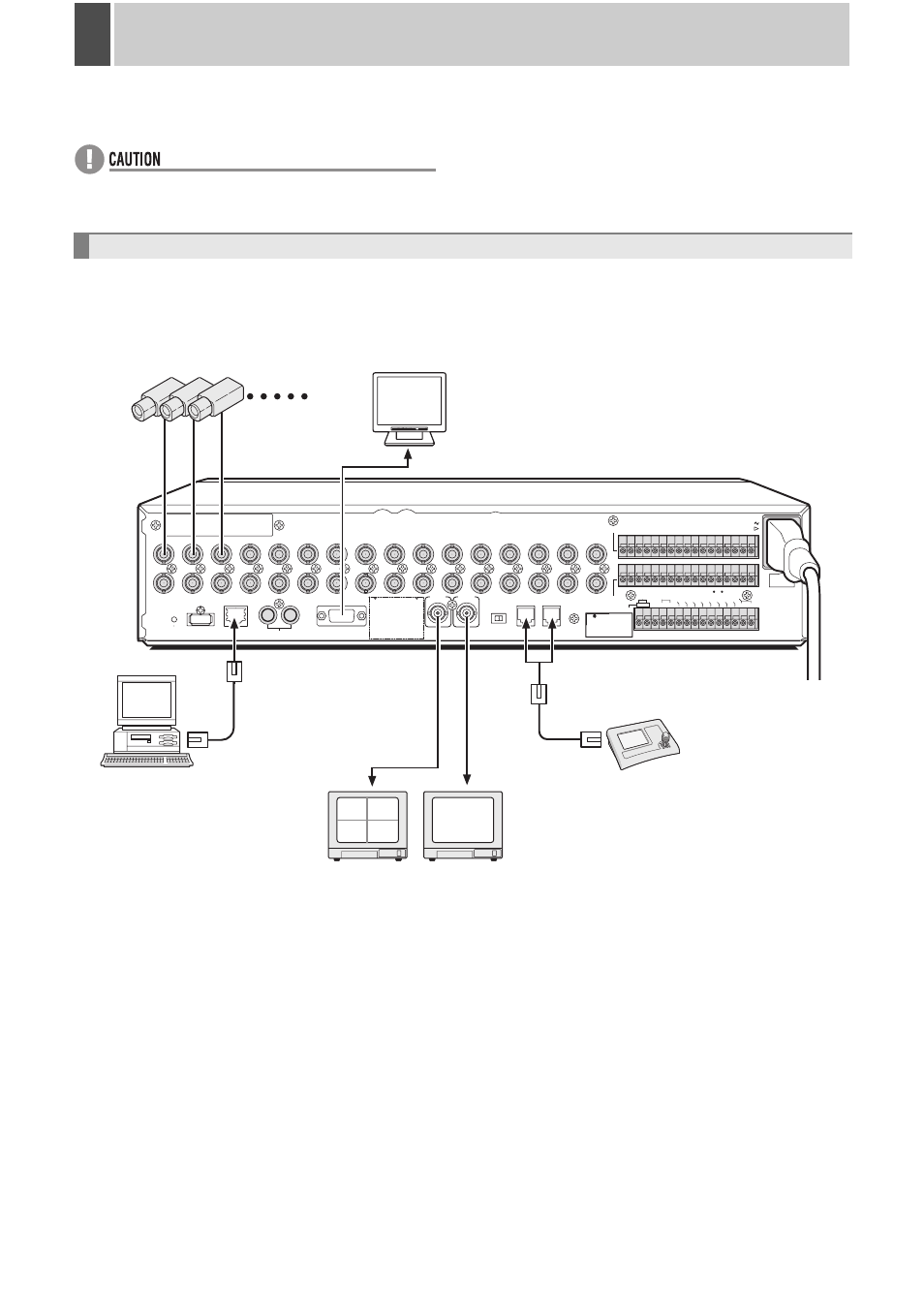
The following diagram shows the connections for cameras, monitors, a PC and a system controller.
Basic connections
IN
OUT
ALL
RESET
USB
LAN
IN
OUT
VGA OUT
MONITOR OUT
DO NOT CONNECT TO PHONE LINE
A
B
MAIN
MON2
AUDIO
1
2
3
4
5
6
7
8
9
10
11
12
13
14
15
16
ALARM IN
SENSOR
ALARM OUT
SELECTABLE
OUTPUT 1 :
NON REC OUT/VIDEO LOSS
OUTPUT 2 :
ARACHIVE FULL/TIMER REC OUT
AC IN
CONTROL
2ND
RS-485/422
EXCEPT SANYO SSP
REMOTE
CLOCK INCLOCK OUT
ALARM RESET
WARNING OUT
FULL
ALARM
OUTPUT 1OUTPUT 2
EXT TIMER IN
OUT
A
B
C
C
1
2
3
4
5
6
7
8
9
10 11 12 13 14 15 16
R1 R2
C
RS-485
SANYO SSP
RS-485
TERMINATE
OFF
ON
02
01
04
03
POWER
MODE
AUTO
MENU
Video input
terminal
PC
(commercially-available)
Monitor
(sold separately)
Video input
terminal
Monitor 2
(sold separately)
120 V – 240 V AC
(50/60 Hz)
Cameras
(sold separately)
1 - 16
System controller
(sold separately)
The RS-485 connector is
connected to A or B according
to the type of cable.
VGA monitor
(sold separately)