Wiring diagrams – Hunter Fan 44668 User Manual
Page 49
49
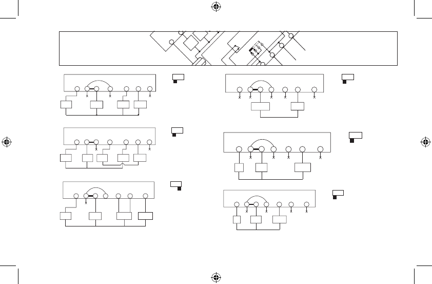
WIRING DIAGRAMS
Y/O
W/B
Y1
G
Fan
Relay
Rc1
Rc
Heat/Cool
24V Supply
Rh
Cool
Contactor
Heat Relay
or Valve
Wallplate
Terminals
Jumper
System
Selector
HG/HE - SSHP
Y/O
W/B
Y1
G
Fan
Relay
Rc1
Rc
Heat 24V
Supply
Rh
Heat Relay
or Valve
Cool
Contactor
Wallplate
Terminals
Cool 24V
Supply
System
Selector
HG/HE - SSHP
Y/O
W/B
Y1
G
Fan
Relay
Rc1
Rc
Heat Pump
24V Supply
Rh
Cool
Mode
Reversing
Valve
Wallplate
Terminals
Jumper
Heat
Mode
OR
Compressor
Contactor
Connect to proper Reversing
Valve Terminal. See Table A
System
Selector
HG/HE - SSHP
Y/O
W/B
Y1
G
Heat Relay
or Valve
Rc1
Rc
Heat 24V or
Millivolt Supply
Rh
Wallplate
Terminals
Jumper
System
Selector
HG/HE - SSHP
Y/O
W/B
Y1
G
Fan
Relay
Rc1
Rc
Heat 24V
Supply
Rh
Heat Relay
or Valve
Wallplate
Terminals
Jumper
System
Selector
HG/HE - SSHP
Y/O
W/B
Y1
G
Fan
Relay
Rc1
Rc
Cool 24V
Supply
Rh
Heat Relay
or Valve
Wallplate
Terminals
Jumper
System
Selector
HG/HE - SSHP
4-Wire Heat/
Cool System
5-Wire Heat/
Cool System
Single-Stage
Heat Pump
System
2-Wire Heat
Only System
3-Wire Heat
Only System
3-Wire Cool
Only System