Servicing the fuse servicing the headlights, Servicing the fuse, Servicing the headlights – Hayter Mowers RT380H User Manual
Page 31: Charging the battery, Removing the bulb
Important: Do not overfill the battery because
electrolyte (sulfuric acid) can cause severe
corrosion and damage to the chassis.
5. Wait 5 to 10 minutes after filling the battery cells.
Add distilled water, if necessary, until the electrolyte
level is up to the Upper line (Figure 36) on the
battery case.
6. Install the battery vent caps.
Charging the Battery
Charging the battery produces gasses that can
explode.
Never smoke near the battery. Keep sparks and
flames away from battery.
Important: Always keep the battery fully charged
(1.260 specific gravity), especially when the
temperature is below 32°F (0°C) to prevent battery
damage.
1. Remove the battery from the chassis; refer to
Removing the Battery.
2. Check the electrolyte level; refer to Checking the
Electrolyte Level.
3. Make sure that the vent caps are installed in the
battery, and charge it for 1 hour at 25 to 30 amps
or 6 hours at 4 to 6 amps. Do not overcharge the
battery.
4. When the battery is fully charged, unplug the charger
from the electrical outlet.
5. Disconnect the charger leads from the battery posts
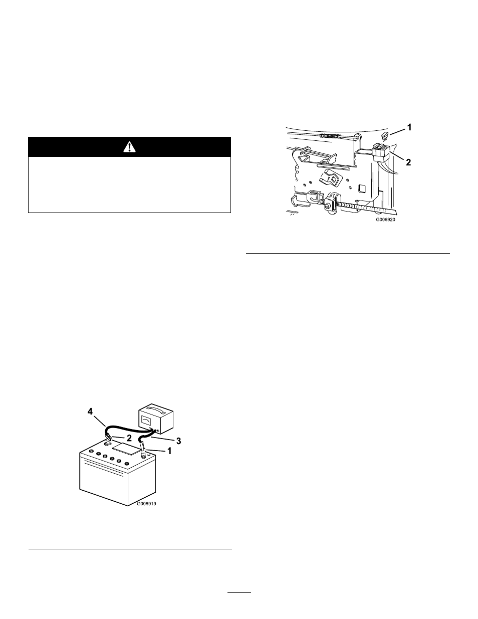
Figure 37
1.
Positive battery post
3.
Red (+) charger lead
2.
Negative battery post
4.
Black (–) charger lead
6. Install the battery in the tractor and connect the
battery cables; refer to Installing the Battery.
Note: Do not run the tractor with the battery
disconnected; electrical damage may occur.
Servicing the Fuse
The electrical system is protected by 10 amp, blade-type
fuses.
1. Pull up on the fuse (Figure 38) to remove it from
the socket.
Figure 38
1.
Fuse
2.
Socket
2. Insert the fuse into socket and push down on the
fuse to install it.
Servicing the Headlights
The headlights use an 1156, automotive-type bulb.
Removing the Bulb
1. Open the hood.
2. Disconnect the wire connectors from both of the
bulb holder terminals.
3. Rotate the bulb holder 1/4 turn counterclockwise
and remove it from the reflector (Figure 39).
31