Warning, Caution, B. connecting to the appliance – Hearth and Home Technologies Cyclone-Cust User Manual
Page 29: C. hot surface ignition wiring
Heat & Glo • Cyclone-Cust • 2061-900 Rev. L • 10/08
29
B. Connecting to the Appliance
Wire 110V to terminal block.
Do NOT wire 110V to valve.
Do NOT wire 110V to wall switch.
• Incorrect wiring will damage this valve.
• Incorrect wiring will override HSI safety lockout
and may cause explosion.
WARNING
• This appliance comes factory wired with a remote
control for operation. The remote can be removed and
the appliance can be wired to run off of a standard
wall switch. Refer to the wiring diagram for more
information.
• Keep wire lengths short as possible by removing any
excess wire length.
• Low voltage and 110 VAC voltage cannot be shared
within the same wall box.
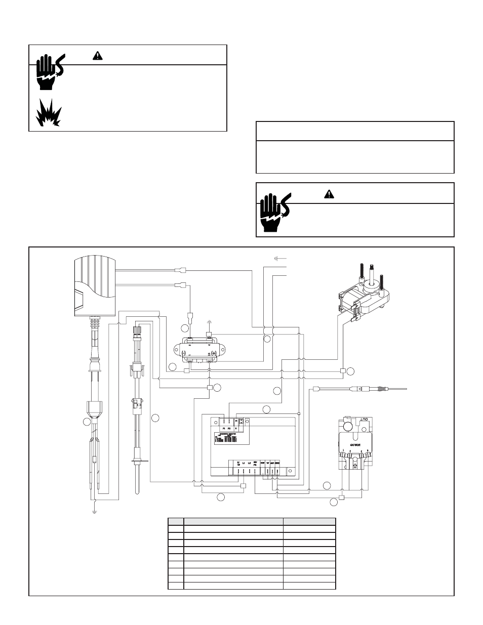
C. Hot Surface Ignition Wiring
This appliance requires a 110 VAC supply to the appli-
ance terminal block for operation. A wiring diagram is
shown in Figure 10.9. This appliance is equipped with a
24V valve.
Optional Accessories Requirements
Wiring for optional accessories should be done now to
avoid reconstruction.
CAUTION
Label all wires prior to disconnection when servicing controls.
Wiring errors can cause improper and dangerous operation.
Verify proper operation after servicing.
Shock hazard.
• Replace damaged wire with type 105º C rated wire.
• Wire must have high temperature insulation.
WARNING
Figure 10.9 Wiring diagram
ITEM
PART DESCRIPTION
COLOR(S)
1
(M)L1 - (M)F1 - (T) 23 - -120V
Black
2
(FT) BTM-IGN-(T)1- +120V
Black/White
3
(V)1 & (V)3 - GND & (T)4
Blue/Green
4
(V)2 & (V)4 - (M)MV1
Red
5
(M) F2 - (FT) TOP
White
6
(M)S1-IGN
White
7
FEMALE RECEPTACLE PLUG
Black/White/Green
8
REMOTE WITH PIGTAIL - (M)W OPTIONAL
Red
9
(M)R - (M)W - (M)P.SW - REM/WS
Red
1
GROUND
(L1) 120-BLACK
(N) NEUTRAL-WHITE
FAN MOTOR
SENSOR
24 VOLT TRANS
CONTROL MODULE
HOT SURFACE IGNITOR
(HSI)
REMOTE
6
2
7
8
3
5
2
9
4
3
1