8 liebert icom® user menu screens, Figure 51 user menu icons, Figure 52 setpoints parameters screen – Emerson Liebert CRV 1 2 3 4 5 6 7 8 9 10 11 12 13 14 15 16 17 18 19 20 21 22 23 24 25 C R 0 2 0 R A 1 C 7 S D 1 8 1 1 E L 1 0 P A User Manual
Page 73: Spare part list, Event log, Liebert icom, 8 liebert icom, User menu screens
Liebert iCOM
®
Control
65
Liebert
®
CRV
™
10.8 Liebert iCOM
®
User Menu Screens
User menus report general cooling unit operations and status. The user menu password is 1490.
The User menu parameter tables in this manual may differ from the display on your cooling unit. The
Liebert iCOM functions with several Liebert Precision Cooling units, each with its own set of control
commands. In addition, the Liebert iCOM control firmware is being updated constantly. As a result,
the User menu parameter tables in this manual may differ from the display on your cooling unit.
Liebert iCOM user manual updates.
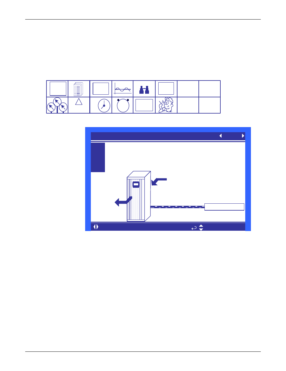
Figure 51 User menu icons
Figure 52 Setpoints parameters screen
Controlling Sensor—This parameter allows the user to select which sensor will be used to
determine the amount of cooling needed. This parameter can select only a single sensor for both the
temperature and fan speed control. Use the Service / Setpoints menu to decouple the operation of fan
speed to the remote sensors and the cooling capacity to the supply sensor.
Temperature Setpoint—This parameter allows the user to select a temperature that the cooling
unit will maintain by applying cooling and or reheats.
Humidity Setpoint—This parameter allows the user to select a humidity that the cooling unit will
maintain by removing or adding moisture to the air.
Spare Part List
Spare Parts—The spare parts lists contains a detailed description and part number that can be used
to order parts for the unit. These part numbers are specific to each model and option installed on the
unit.
Event Log
Event Log—The event log displays all events and actions that have been generated by the unit.
When multiple units are networked you will see the event log of the whole system. Each event shows
the unit that generated the alarm, time and date stamp, a description and the event type
EVENT
LOG
°C / °F
% RH
SET
SET
1 2
3
9
6
SET
ALARMS
!
ACTIVE
ALARMS
1 2 3 4
h
RACK
VIEW
User Menu
password: 1490
U101
U102
U103
U104
PASSWORD (Actual Level 0)
????
Controlling Sensor
Remote Sensor
Temperature Setpoint
68°F
Humidity Setpoint
45%
SETPOINTS
UNIT 01
for next/previous unit
to select parameter
Supply Sensor
Return Sensor
68° 45%
Remote Sensor