1 general layout, Table 5 condenser positioning, General layout – Emerson Liebert CRV 1 2 3 4 5 6 7 8 9 10 11 12 13 14 15 16 17 18 19 20 21 22 23 24 25 C R 0 2 0 R A 1 C 7 S D 1 8 1 1 E L 1 0 P A User Manual
Page 28: Table 5, Condenser positioning, Table 6
Refrigerant Connections
Liebert
®
CRV
™
20
6.2.1 General Layout
1. Piping must be Type ACR copper tubing and sized per Tables 7, 8, 9 and 10.
Use the shortest possible refrigeration pipelines to minimize the total charge of refrigerant and
the number of pressure drops.
2. Minimize the number of bends and make the bends the largest radius practical to prevent
constricting refrigerant flow.
3. Insulate the piping as specified in Table 5. If the pipes are installed next to electrical cables, they
must be isolated from the building using vibration-isolating supports to avoid damage to cable
insulation.
4. There must be at least one inch (25mm) separation between the gas and liquid pipelines. If this is
not possible, insulate both lines.
5. Support both horizontal and vertical pipes with vibration-damping clamps, which include rubber
gaskets. Place these clamps every 5 to 7 ft. (1.5 to 2m).
NOTE
All field-installed piping must comply with applicable national, state and local codes.
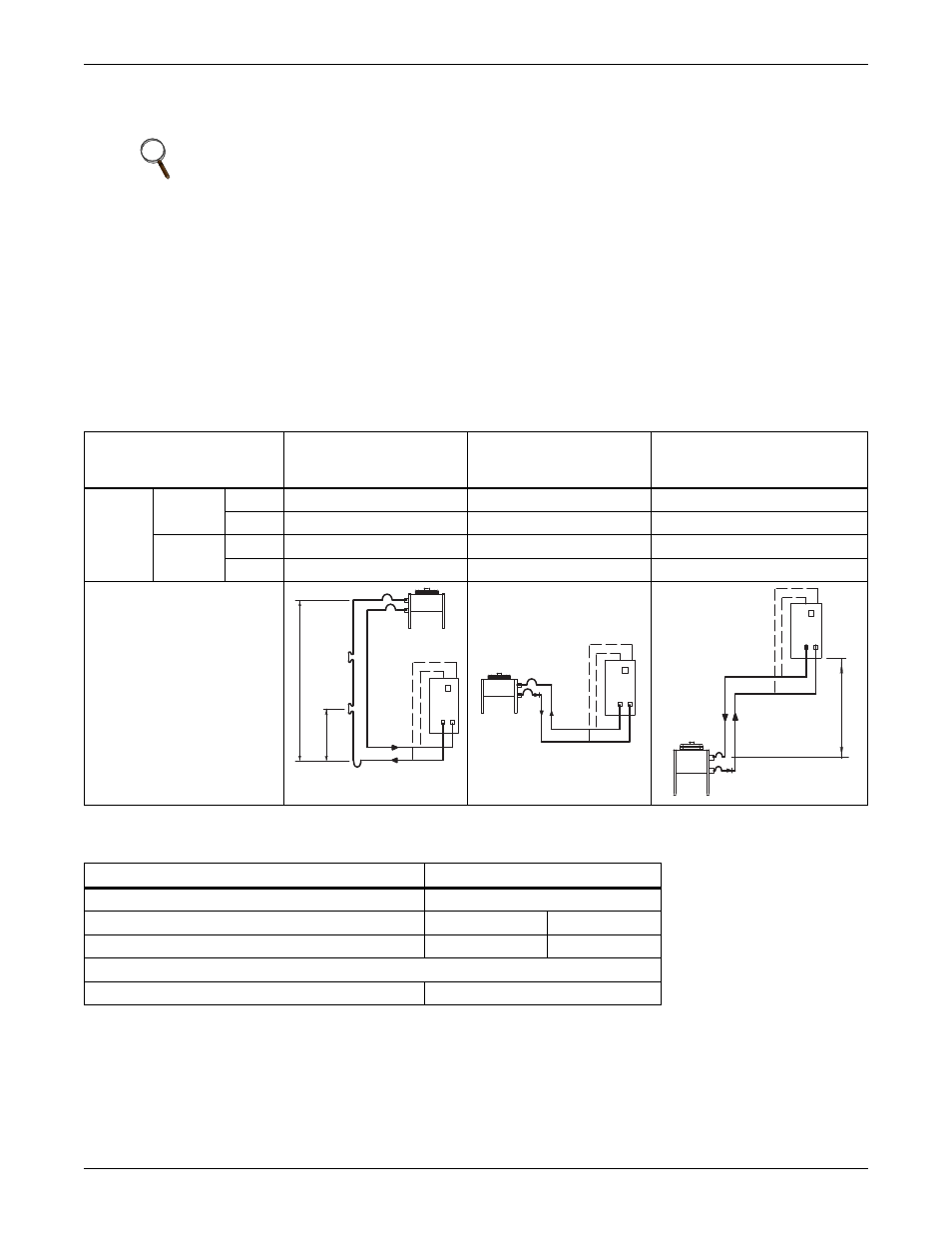
Table 5
Condenser positioning
Condenser
Position
Condenser Above
Liebert CRV
Condenser and
Liebert CRV
at Same Level
Condenser Below
Liebert CRV
(Not Recommended)
Insulation
Discharge
Line
Indoor
necessary
necessary
necessary
Outdoor only for aesthetic reasons
only for aesthetic reasons
only for aesthetic reasons
Liquid
Line
Indoor only for aesthetic reasons
only for aesthetic reasons
no (expose to cold under-floor air)
Outdoor only for aesthetic reasons
only if exposed to sun
only if exposed to sun
Layout
Table 6
Liebert CRV position relative to the remote condenser
Parameter
Maximum Distances, ft. (m)
From Liebert CRV to condenser
300 (91.4) equivalent length
From Liebert CRV to VFD condenser
Above: 60 (18.3)
Below: 15 (4.5)
From Liebert CRV to Liebert Lee-Temp
™
condenser
Above: 60 (18.3)
Below: 0 (0)
Requirements
Oil traps on vertical line of gas refrigerant
Every 15 (4.6)
15 ft. (4.6m)
(See *)
Gas
Liquid
* Oil traps every 15 ft. (4.6m)
of vertical piping
Room Unit
(See **)
Gas
Liquid
Room Unit
Liquid
Room Unit
(See**)