Emerson Liebert CRV 1 2 3 4 5 6 7 8 9 10 11 12 13 14 15 16 17 18 19 20 21 22 23 24 25 C R 0 2 0 R A 1 C 7 S D 1 8 1 1 E L 1 0 P A User Manual
Page 100
Liebert iCOM
®
Control
Liebert
®
CRV
™
92
Figure 85 Rack Overview, Page 1
This screen shows the rack label assigned to each rack and the temperature associated with the rack
sensor. This screen shows the relative distance between the Liebert CRV and each rack sensor.
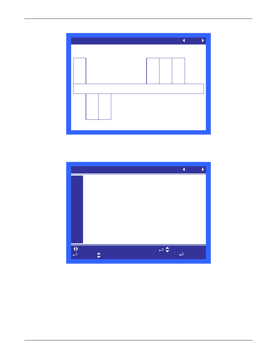
Figure 86 Rack Setup, Page 1
Rack Sensors are automatically detected when connected and set to “Control.” A maximum of 10
2T sensors can be connected; the control automatically detects the type.
Control—The Liebert CRV is using the sensor for temperature control.
Reference—The sensor value is shown, but not used for temperature control.
Disable—No sensor connected.
Rack Overview (page 1 of 1)
UNIT 01
All temperatures shown in °F
Cold Aisle
1
77
CC21
2
78
BB01
3
78
BB02
4
77
BB03
78
EC50
5
EC51
6
to change parameter
for next/previous unit
to select parameter
to confirm
then
S901
S902
S903
S904
S905
S906
S907
S908
S909
S910
S911
PASSWORD Actual Level 0)
????
Remote Sensor Node 01
Control
Remote Sensor Node 02
Control
Remote Sensor Node 03
Control
Remote Sensor Node 04
Control
Remote Sensor Node 05
Control
Remote Sensor Node 06
Control
Remote Sensor Node 07
Disable
Remote Sensor Node 08
Disable
Remote Sensor Node 09
Disable
Remote Sensor Node 10
Disable
RACK SETUP (page 1 of 3)
UNIT 01