Mechanical specifications, Parameter value units limits, Environmental chacteristics (design to meet) – RF-Links Wideband Microwave Amplifier 40W (2000-4000 MHz) User Manual
Page 2: Paramer symbol min typ max unit, Typical performance plots
Current Consumption @ P
OUT
= 35W
I
DD
7.5 10 Amp
Quiescent Current
I
DQ
4.0
6.0
Amp
Switching Time @ 1kHz TTL, P
IN
= 0dBm
T
ON
/ T
OFF
5.0 µs
Mechanical Specifications
Parameter
Value
Units
Limits
Dimensions
5.65 x 12.5 x 1.75
Inch
Max
Weight 2.0
lb.
Max
RF Connectors Input/Output
Type-SMA, Female
DC Interface Connector
D-Sub 9-Pin, Male
Cooling
External Heatsink
Environmental Chacteristics (Design to Meet)
Paramer
Symbol
Min
Typ
Max
Unit
Operating Case Temperature
T
C
-20
+70
°C
Storage Temperature
T
STG
-40
+85 °C
Relative Humidity (non-condensing)
RH
95
%
Altitude (MIL-STD-810F Method 500.4)
ALT
30,000 Feet
Vibration/Shock
MIL-STD-810F - Method 514.5/516.5 – Proc I
VI/SH
Airborne
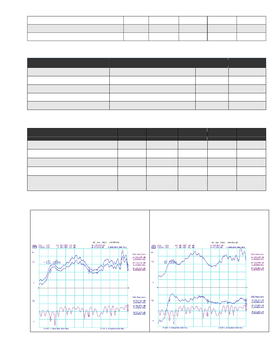
Typical Performance Plots
Plot 1 – Small Signal Gain and P1dB Gain
Top Curve: Small Signal Gain @ PIN = -20dBm
Middle Curve: Power Gain @ P1dB, PIN = -16dBm
Reference: 52dB, 2dB/div.
Bottom Curve: Input Return Loss
Reference: 10dB, 10dB/div
Plot 2 – Small Signal Gain and P
SAT
Top Curve: Small Signal Gain @ P
IN
= -20dBm
Bottom Curve: Power Gain @ P
SAT
, P
IN
= 0dBm
Reference: 51dB, 2dB/div.
Middle Curve: Input Return Loss
Reference: 10dB, 10dB/div.
Copyright © 2001-2014 RF-LINKS