ProSoft Technology 5202-DFNT-MCM4 User Manual
Page 27
MCM Protocol Configuration
MCM ♦ ProLinx Gateway
Driver Manual
Modbus Master/Slave
ProSoft Technology, Inc.
Page 27 of 80
October 16, 2009
3.2
[Modbus Port X Commands]
The [Modbus Port X Commands] (where X can be 0, 1, 2, or 3) sections of the
CFG file are used to define a Master serial port Command List. This list holds the
parameters needed to poll slave devices attached to a Master port. The gateway
supports eight types of commands. This permits the gateway to interface with a
wide variety of Modbus slave devices.
The Command List is formatted differently than the other sections of the
configuration file. Commands are present in a block between the labels START
and END. These labels inform the program where the list resides. The module's
program will parse all commands after the START label until it reaches the END
label or until the command count entered for the port is reached.
The format of each command in the list is the same. The parameter values
entered determine the operation to be performed. The following table lists
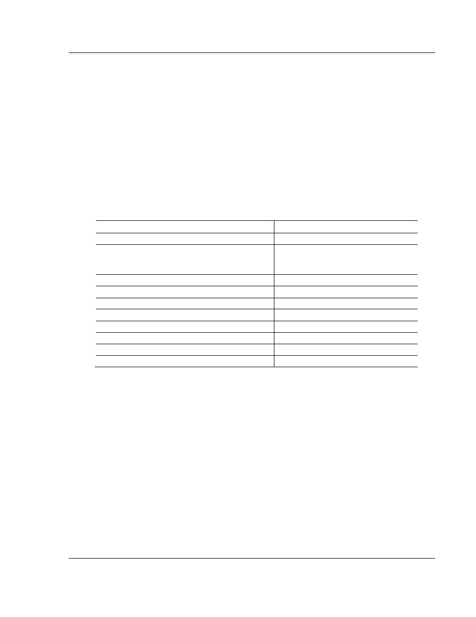
supported Modbus Functions Codes and outlines their format.
Module Information Data ←
→
Device Information Data
Column
#
1 2 3 4 5 6 7 8
Modbus
Function
Code
Enable
Code
Internal
Address
Poll
Interval
Time
Count Swap
Code Slave Node Function
Code
Device
MODBUS
Address
FC1 Code Bit Seconds
Count 0 Address 1 Bit
FC2 Code Bit Seconds
Count 0 Address 2 Bit
FC3 Code
Register
Seconds
Count Code
Address 3 Register
FC4 Code
Register
Seconds
Count 0 Address 4 Register
FC5 Code Bit Seconds
Count 0 Address 5 Bit
FC6 Code
Register
Seconds
Count Code
Address 6 Register
FC15 Code Bit Seconds
Count 0 Address 15 Bit
FC16 Code Register
Seconds
Count Code Address 16 Register
The first part of the record is the Module Information, which relates to the ProLinx
module and the second part contains information required to interface to the
Modbus slave device. Refer to the Modbus protocol specification and slave
device documentation for a full discussion of each function. The Device Modbus
Address information can be found in the documentation for the slave device.
Command list example:
[PORT 0 COMMANDS]
# INTERNAL POLL SWAP SLAVE FUNCTION DEVICE
# ENABLE ADDRESS INTERVAL COUNT CODE NODE CODE ADDRESS
START
1 0 0 10 0 1 3 0
1 0 0 10 0 1 16 10
END