Avago Technologies MegaRAID SAS 9260-4i User Manual
Page 13
LSI Corporation
- 13 -
MegaRAID LSIiBBU07 Intelligent Battery Backup Unit Quick Installation Guide
October 2011
MegaRAID LSIiBBU07 Intelligent Battery Backup Unit Quick Installation Guide
Connecting a Remote LSIiBBU07 Unit on the System Chassis to a Board-to-Board Cable
Adapter Card on a RAID Controller
Connecting the Cable between the Board-to-Board Cable Adapter Card on the RAID Controller and the
Remote LSIiBBU07 Unit on the System Chassis
Follow these steps to connect the cable between the adapter card on the RAID controller and the LSIiBBU07 unit.
1.
Mount the LSIiBBU07 unit to the chassis of your computer based on the location and the type of
mounting option.
2.
With the controller on a flat, clean, static-free surface, ground yourself, and make sure that the system
is grounded.
3.
Remove the cable included in the Remote Battery Kit (sold separately).
4.
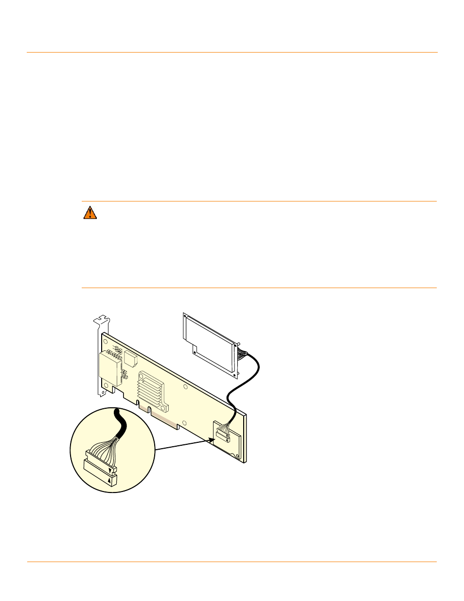
Insert one end of the cable into the 20-pin J2 connector on the LSIiBBU07 unit and the other end of the cable into
the 20-pin J1 connector on the board-to-board cable adapter card, as shown in the following figure.
Black triangles on the connectors help you install the connectors correctly. Align the black triangles on the cable
connectors to make sure that they are connected correctly.
Figure 7 Connecting the LSIiBBU07 Unit Remotely to the RAID Controller
CAUTION Damage to the battery backup unit will occur when power is applied to the system if the cable
assembly connectors are installed backwards in either the JT1 board-to-board connector or the J2 battery
connector. The cable connectors are polarized, and the keying features of the connector are designed to
allow the connectors to be attached in only one orientation. The cable end inserts into the connector with
only minimal resistance. Even with the keying features, if excessive force is used, it is possible to install
these connectors incorrectly. To assist in correct alignment, the small triangles that designate pin 1 on
each connector have been marked in black. Make sure that these triangles line up as shown in the
illustrations. Also, the wire that connects to pin 1 of each end of the cable assembly is yellow on most
LSI cables.
85021-13