Earth resistivity measurement – Amprobe Multitest-1000 Continuity-Tester User Manual
Page 64
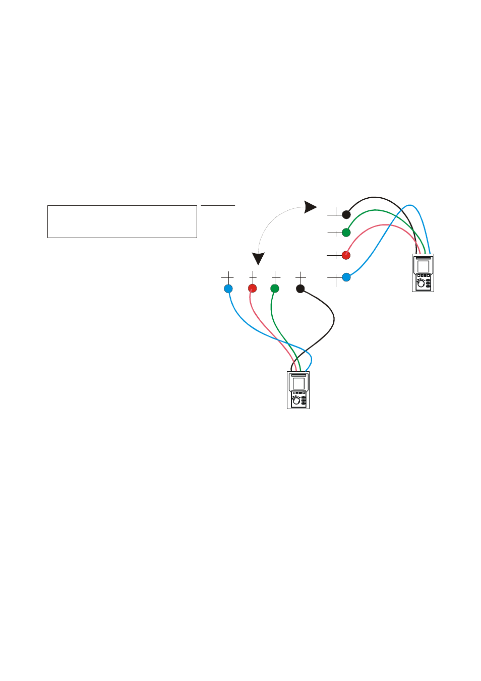
11.6. EARTH RESISTIVITY MEASUREMENT
PURPOSE OF THE TEST
This test measures the resistivity value of the ground in order to define the type of rods to
be used.
EQUIPMENT PARTS TO BE TESTED
For the resistivity test admissible values do not exist. The various values measured by
positioning the rods at increasing distances “a” must be specified in a graph. According to
the resulting curve, suitable rods will be chosen. Metal parts buried in the ground, such as
pipes, cables or other rods, can affect the test results. In case of doubt take a second
measurement positioning the rods at an equal distance "a", but rotating their axis by 90°.
Black
Bl
ac
k
B
lu
e
Blu
e
Green
G
re
en
Re
d
R
ed
a
a
a
a
a
a
90°
2
90°.
compared to the previous measurement
the rods are rotated by
2° Measurement:
The resistivity value is calculated with the following formula:
ρ=2πaR
where:
ρ= specific resistivity of the ground
a= distance between the rods (m)
R= resistance measured by the instrument (
Ω)
This measuring method defines the specific resistance up to the depth corresponding to
the approximate distance “a” between the rods. If you increase the distance “a” you can
reach deeper ground layers and check the ground homogeneity. After several
ρ
measurements, at growing distances “a”, you can trace a profile like the following ones,
according to which the most suitable rod is chosen.