Warning – Amprobe Multitest-1000 Continuity-Tester User Manual
Page 20
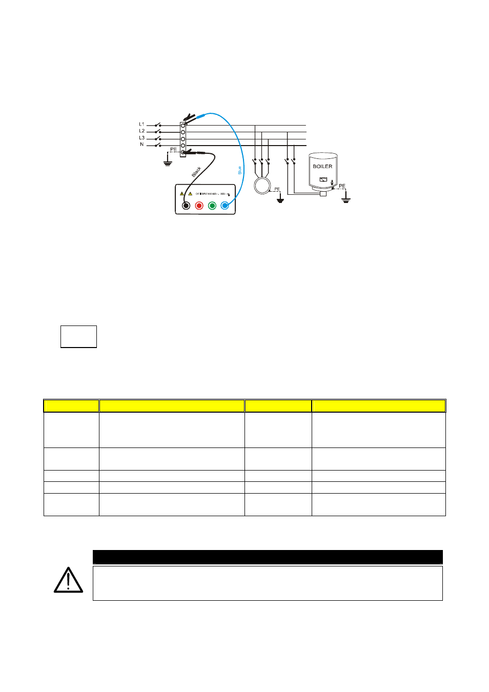
4.2.1. Procedure for measuring insulation resistance in any mode
1. Select the desired mode by means of the FUNC key.
2. Connect the black and blue cables to the instrument input terminals T1 and T4
respectively.
B2
B3
B4
B1
M
Insulation between phase and earth in an electrical
installation using untied cables.
3. If the cables supplied with the instrument are not long enough for the measurement you can
extend the blue cable.
4. Connect the instrument terminals to the object that is to be submitted to the insulation
test after disconnecting the circuit under test and all the relative loads (see
previous picture).
5.
By pressing the U
n
key select the test voltage suitable for the type of
test to be carried out (see table). The values to be selected are:
• 50V (test on telecommunication system)
• 100V
• 500V
• 250V
• 1000V
Standard
Brief description
Test voltage
Maximum limit value
CEI 64-8/6
Systems SELV or PELV
Systems up to 500V (Civil installations)
Systems over 500V
250VDC
500VDC
1000VDC
> 0.250M
Ω
> 0.500M
Ω
> 1.0M
Ω
CEI 64-8/4
Floor and wall insulation in civil installations
Floor and wall insulation in systems over 500V
500VDC
1000VDC
> 50k
Ω (if V<500V)
> 100k
Ω (if V>500V)
EN60439
Electrical panel boards 230/400V
500VDC
> 230k
Ω
EN60204
Electrical equipment of machines
500VDC
> 1M
Ω
CEI 64-4
Floor insulation in medical rooms
500VDC
<1M
Ω (if the floor is at least 1 year old)
<100M
Ω (if the floor is at least 1year old)
Test voltage values and the relative maximum limit values for the most common kinds of test.
WARNING
If “Measuring” is displayed the instrument is performing the measurement.
During this phase do not disconnect the test leads, as the circuit under test
may remain charged at a dangerous voltage due to the parasite capacitance
U
n
DIST