Dmiiis, Where – Amprobe DM-111S Current-Data-Logger User Manual
Page 58
DMIIIS
EN - 56
Note:
It is to be noted that the expression of the phase Reactive Power with non sine waveforms,
would be wrong. To understand this, it may be useful to consider that both the presence of
harmonics and the presence of reactive power produce, among other effects, an increase
of line power losses due to the increased current RMS value. With the above given relation
the increasing of power losses due to harmonics is added to that introduced by the
presence of reactive power. In effect, even if the two phenomena together contribute to the
increase of power losses in line, it is not true in general that these causes of the power
losses are in phase between each other and therefore can be added one to the other
mathematically.
The above given relation is justified by the relative simplicity of calculation of the same and
by the relative discrepancy between the value obtained using this relation and the true
value.
It is to be noted moreover, how in case of an electric installation with harmonics, another
parameter called distorted Power Factor (dPF) is defined. In practice, this parameter
represents the theoretical limit value that can be reached for Power Factor if all the
harmonics could be eliminated from the electric installation.
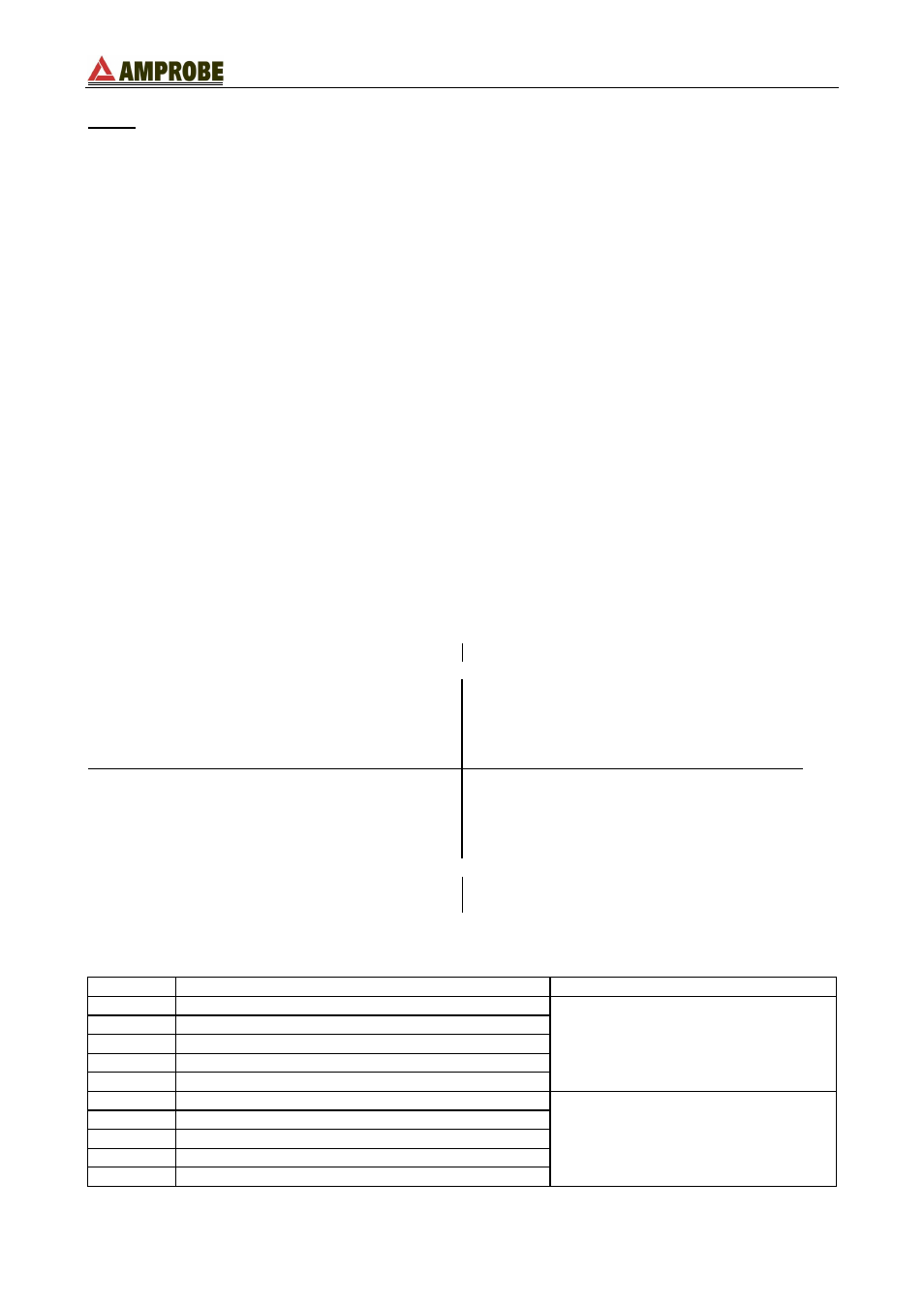
16.3.1. Conventions on powers and power factors
As for the recognition of the type of reactive power, of the type of power factor and of the
direction of the active power, the below conventions must be applied. The stated angles
are those of phase-displacement of the current compared to the voltage (for example, in
the first panel the current is in advance from 0° to 90° compared to the voltage):
Equipment under test = Inductive Generator
Equipment under test = Capacitive Load
90°
180°
P+ = 0
Pfc+ = -1
Pfi+ = -1
Qc+ = 0
Qi+ = 0
P - = P
Pfc - = -1
Pfi - = Pf
Qc- = 0
Qi - = Q
P+ = P
Pfc+ = Pf
Pfi+ = -1
Qc+ = Q
Qi+ = 0
P - = 0
Pfc - = -1
Pfi - = -1
Qc- = 0
Qi - = 0
0°
P+ = 0
Pfc+ = -1
Pfi+ = -1
Qc+ = 0
Qi+ = 0
P - = P
Pfc - = Pf
Pfi - = -1
Qc- = Q
Qi - = 0
P+ = P
Pfc+ = -1
Pfi+ = Pf
Qc+ = 0
Qi+ = Q
P - = 0
Pfc - = -1
Pfi - = -1
Qc- = 0
Qi - = 0
270°
Equipment under test = Capacitive Generator
Equipment under test = Inductive Load
where:
Symbol
Significance
Remarks
P+
Value of the active power +
Positive parameter
(user)
Pfc+
Capacitive power factor +
Pfi+
Inductive power factor +
Qc+
Value of the capacitive reactive power +
Qi+
Value of the inductive reactive power +
P-
Value of the active power -
Negative parameter
(generator)
Pfc-
Capacitive power factor -
Pfi-
Inductive power factor -
Qc-
Value of the capacitive reactive power -
Qi-
Value of the inductive reactive power -