6 back panel layout – EverFocus EZ650 User Manual
Page 12
12
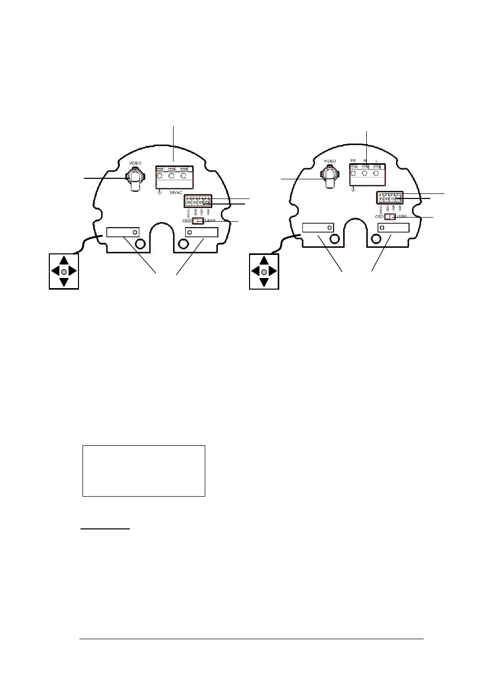
1.6 Back Panel Layout
1. Video Output Connector
Connect the video output of the camera to a color monitor or other video devices through a 75
Ohm type coaxial cable with BNC female connector at backside of the camera.
2. Power Input Terminal
Connect the appropriate power to each model. N/L is used to connect to power in. PE is a
ground pin.
3. RS-485 communication and External IR power control pin
PIN definition:
a. TXD (RS485 +): for keyboard controlling.
b. RXD (RS485-): for keyboard controlling.
4. Power for IR illuminator
Referring to above figure, pin 12VDC and GND are defined as below:
a. GND: Ground
b. 12VDC: provide power source for IR illuminator (IR illuminator is optional).
110V~240VAC model (for
110V ~240V Power only)
24VAC model (for 24VAC
Power Only)
485-
485+
GND
12VDC
1
4
3
6
2
7
3
2
5
4
6
7
1
5
- Mini Box Camera EQH5102 (18 pages)
- EHD300N (12 pages)
- EZH5040 (24 pages)
- ED200E (9 pages)
- ED560 (47 pages)
- EAN EDN850H (60 pages)
- EZ550 (44 pages)
- EAN850A (60 pages)
- ED700 (7 pages)
- ED200 (12 pages)
- Color Rugged Dome Camera EHD350 (13 pages)
- ED300 Series (13 pages)
- ECD230 (6 pages)
- EZ-VF325NH (9 pages)
- ED335 (18 pages)
- EDN800 (43 pages)
- SPEED DOME EPTZ900 (42 pages)
- EHD360 (7 pages)
- EHD150 (14 pages)
- ENVS1600 (115 pages)
- SPEED DOME EPTZ1000 (37 pages)
- NEV10 EZN850 (58 pages)
- ECZ230E (6 pages)
- ED230 (7 pages)
- EHD650 (25 pages)
- Weatherproof Long Range IR Camera 330E (15 pages)
- EI350 (8 pages)
- FULL HD-CCTV CAMERA EQH5200 (15 pages)
- EAN900 (44 pages)
- EZ600/B (2 pages)
- EQ610 (26 pages)
- Megapixel Over Coax Without Networking EDR-HD-2H14 (4 pages)
- EZ-PLATECAM2 (19 pages)
- ED610 (32 pages)
- EZ350 (10 pages)
- EPTZ3100I (75 pages)
- Day / Night Speed Dome Camera EPTZ 100 (48 pages)
- IP 99 Series (32 pages)
- ECD360AV (7 pages)
- 560 TVL Color Mini Dome Camera ED350 (10 pages)
- EAN-1350 (59 pages)
- EZ630 (33 pages)
- EBD430 (15 pages)
- EQ120 (13 pages)