Power supply interior status light fault codes, 4 power supply interior status light fault codes – Retrotec Blower Door User Manual
Page 57
Page 57 of 87
©Retrotec Inc. 2015
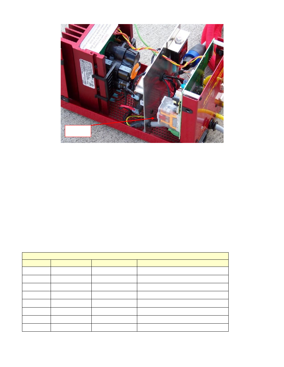
Figure 35: Relay box in the variable speed drive.
Ensure that the relay is seated properly. The relay may require gluing with silicon glue. The case cover screws will
need to be removed in order to access the relay. Remove the tamper seal, if so equipped. Remove the front left
side and right side, top and bottom screws. Also remove the rear left and right bottom screws. Loosen the rear top
screws, but do not remove them. The cover can then be swung upward.
8.4
Power supply interior status light fault codes
You can see the lights by looking through the holes in the right side of the power supply. The lights are toward the
rear of the power supply.
The PWR (Power) LED is the LED to the right. This LED is solid green when AC is applied to the power supply.
The ST (Status) LED is the LED to the left. This LED will indicate an abnormal or fault condition. The information can
be used to diagnose an installation problem such as incorrect input voltage, an overload condition, and power
supply output mis-wiring. It will also provide a signal which informs the user that all power supply and
microcontroller operating parameters are normal.
Table 7: Power supply status light indications
Status LED
Color
Flash Rate
Power supply Status
Color and Sequence After Recovered Fault
Green
1 sec on/off
Normal operation
--
Red
On
Overload
Green
Red
¼ sec on/off
Power supply timed out --
Red
1 sec on/off
Short circuit
--
Red/Yellow
¼ sec on/off
Under voltage
Red/Yellow/Green
Red/Yellow
1 sec on/off
Over voltage
Red/Yellow/Green
Yellow
On
Stop
--
Yellow
0.04 s on/0.06 s off
Phase Loss Detection
--
Relay
Box