Remote Processing RPC-220 User Manual
Page 47
TECHNICAL SPECIFICATIONS
SECTION 15
Page 15-3
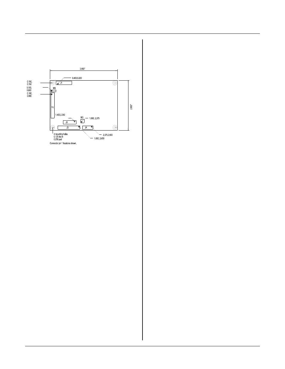
Figure 15-1 Board Size and Connector Placement
Connector Positions
Leader s in Figure 15-1 show the location of pin 1 for J1
- J5. P in 2 is shown imm ediately next to pin 1 as a
circle. View is from component side of the RPC-220.
Four mounting h oles are 0 .15 0" fr om eac h corne r. Hole
diameter is 0.125" and is in a 0.250" diameter pad.