Calibration, Application programs, J1 analog i/o connector pin out – Remote Processing RPC-220 User Manual
Page 37
ANALOG INPUT
SECTION 11
Page 12-4
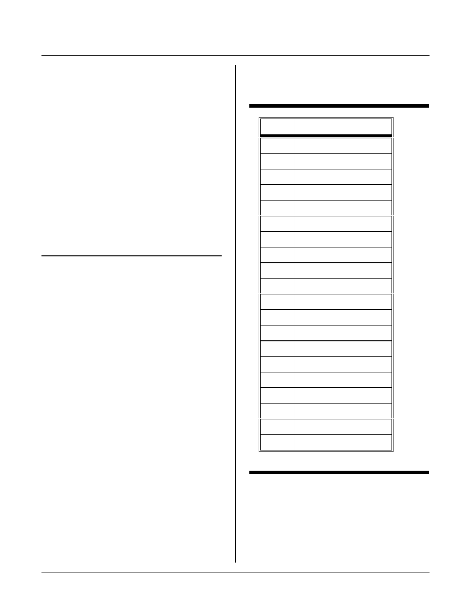
J1 Pin
N a m e
1
Analog inp ut 0
2
Ground
3
Analog inp ut 1
4
Ground
5
Analog inp ut 2
6
Ground
7
Analog inp ut 3
8
Ground
9
Analog inp ut 4
10
Ground
11
Analog inp ut 5
12
Ground
13
Analog inp ut 6
14
Ground
15
Analog inp ut 7
16
Start convert input
17
Analog ou tput 0
18
+ V (
.
8.5 volts)
19
Analog ou tput 1
20
-V (
.
-8 volts)
CALIBRATION
R4 is used to adjust the maximum, or reference voltage.
Its location is shown in Figure 11-1 above. Norm ally,
the reference is 5.000 volts. You can adjust R4 so the
referen ce voltage is between about 4. 8 and 5. 2 volts.
Adjusting the refer ence voltage to 5. 12 volts makes easy
binary to voltage conversion (5 mv/bit) for display or
over r ange cond ition on a sensor output.
To calibr ate or othe rwise a djust the refe rence, connect a
volt meter between J1-2 and R3, pin 1. If the voltage
you are measur ing is about 9 volts, then you pr obably
have the wrong side of R3. Adjust R4 for the desired
v o lt a ge . A d ju s tm e n t i s b e st ac c om p li sh e d u s in g a 3 m m
screw driver slot.
APPLICATION PROGRAMS
Program s are in the ANAL OG directory.
F i le n am e
Description
AIN220-1. C
Simple polle d mode. All channe ls
printed out. Prints out as a real
voltage. i.e. 3.74
AIN220-2. C
Same as above except interrupt driven.
Int handler gets data and puts it into a
global variable.
AIN220-3. C
Interrupt driven, but triggered
externally at J1-16 (CPU STA DC pin)
on a rising pulse. Result for channel
one only printed.
F u n ct io n s a r e na m e d A I N (channel), where channel is
from 0 to 7. Return values are always in the 0 to 1023
range.
To convert a returned number to a voltage (reference set
to 5.000 volts), m ultiply the result by .004883. The
Dunfield C compiler does not support floating point
directly. All application programs show a w ay to print
out a value as if it were floating point by using 'long'
data types.
Reference
1
Phillips Sem iconductor s Application note
EIE/ AN93017, page 6-196 ff.
J1 ANALOG I/O CONNECTOR PIN OUT
The table below is a pin out for analog connector J1.