Installing the cveq 100 d/sveq 100 d, Preparing the site and installing the wall box, Mounting the line driver – Extron Electronics CVEQ 100 Series User Manual
Page 14: Installing the cveq 100 d/sveq 100 d -14, Installation, cont’d
CVEQ 100 and SVEQ 100 Series • Installation
Installation, cont’d
2-14
CVEQ 100 and SVEQ 100 Series • Installation
2-15
Installing the CVEQ 100 D/SVEQ 100 D
The CVEQ 100 D and SVEQ 100 D are wall-mounted products
and can be mounted into an electrical wall box. This section
includes site preparation, wall box installation, and the
mounting of the line driver in the wall box.
N
The line driver must be installed into an Underwriters
Laboratories (UL) approved electrical wall box. The
box is not included with the line driver; the installer is
responsible for obtaining and installing the box.
Preparing the site and installing the wall box
Choose a location that allows cable runs without interference.
Allow enough depth for both the wall box and the cables. You
may need to install the cables into the wall or conduits before
installing the line driver.
The line driver can be installed in a standard one-gang electrical
wall box. The installation must conform to national and local
electrical codes. A dimensional drawing and a cutout template
of the line driver are provided in appendix B of this manual.
N
The cutout template shown in appendix B is not full size.
Pay attention to the measurements shown on the template.
1
.
Mark the guidelines for the opening on the wall.
•
If the line driver will be installed in a wall box, place
the box against the installation surface and draw a line
on it around the outside of the box.
•
If the line driver will be installed without a wall box
(fastening it directly to the wall), measure and mark
the surface for the cutout area indicated in the cutout
template.
2
.
Cut out the material from the marked area.
3
.
Check the opening size by inserting the wall box (if used)
or the line driver (if no box is used) into the opening. The
box and line driver should fit easily into the opening.
Enlarge or smooth the edges of the opening if needed.
4
.
Feed cables through the wall box punch-out holes, and
secure them with cable clamps to provide strain relief.
5
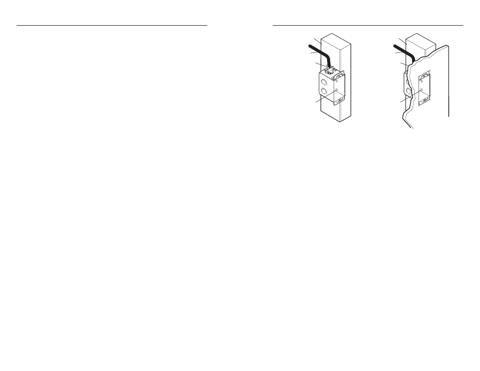
.
Insert the wall box into the opening, and attach it to the
wall or stud using nails or screws. The front edge should
be flush with the outer wall surface. See the following
illustration.
Installation Cable
Cable Clamp
Wall Stud
Installation Cable
Cable Clamp
Wall Stud
Screws or Nails
Screws or Nails
Attaching the wall box to a wall stud
If attaching the wall box to wood, use four #8 or #10 screws
or 10-penny nails. A minimum of ½" (1.3 cm) of screw
threads must penetrate the wood.
If attaching the wall box to metal studs, use four #8 or
#10 self-tapping sheet metal screws or machine bolts with
matching nuts.
Mounting the line driver
Before mounting the line driver and if has not already been
tested, test the system to make sure that the connections and
settings are correct. See "Testing and troubleshooting" in this
chapter.
If the system is operating correctly, the line driver can be
installed in the wall. Adjust the gain and equalization, and set
the Audio Out switch to Stereo or Dual Mono before fastening
the line driver into the wall box. The controls and cables will
be inaccessible after installation. See “Rear Panel Features
and Operation" in chapter 3 for details about settings and
adjustments.
Continue mounting the line driver by following the steps below.
1
.
Remove power from the line driver by disconnecting the
power supply from the AC source.
2
.
Connect the output cables to the rear of the device.
3
.
Place the line driver through the opening in the wall and
into the wall box. Take care not to damage the output
cable(s), which fit behind the line driver at the back of the
wall box.