Fig.1 fig.3 fig.4, Operating - cars & vans – Sealey GA50 User Manual
Page 2
4. OPerating - Cars & Vans
nOte: Cars & Vans. Prior to use check vehicle manufacturers recommendations relating to loading. check that tyre pressures are correct.
4.1 Ensure that the vehicle is on a smooth level surface with the wheels pointing straight ahead. (Do not back the vehicle into position).
4.2 Position the laser unit against the offside front wheel (see fig.1) and adjust the height of
the contact bars by fixing them in which ever of the five preset positions is closest to a
horizontal line through the centre of the wheel. At the same time adjust the side to side
positioning of the contact bars so that they touch the sidewall of the tyre either side of the
rim. Position the tips of the contact bars to touch the centre of the sidewalls at the greatest
point of curvature. Avoid any ribs or raised lettering on the tyre side wall.
4.3 the contact bars of the mirror unit should now be set up to the same height and width as
the laser unit. to do this remove the laser unit from its position on the tyre and place it
in front of the mirror unit to make the necessary adjustments.
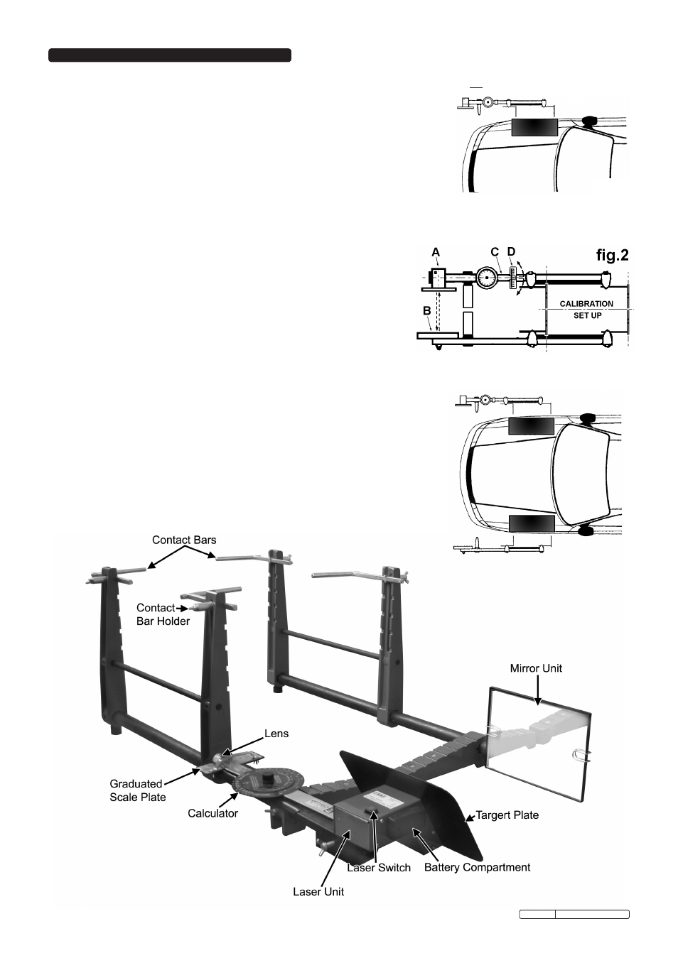
4.4 When the contact bar arrangements on both units match, proceed to calibrate the gauge.
(
see calibration set - up in figure 2).
4.5 stand both units close together so that the tips of the contact bars are touching. the mirror unit (B) should be vertical. (check the built
in spirit level and adjust accordingly). If the laser beam is not visible on the target plate loosen the thumb screw and tilt the laser
unit until the beam is visible on the target plate. (see fig.4).
4.6 Move the pointer arm (see fig.2-c) until the laser beam is visible on the
vertical centre line in between the two bold arrows.
4.7 the lens attached to the end of the pointer arm should now be positioned over
the zero mark on the graduated scale plate. (see fig.2-D) If it is not, slacken
the two wing nuts (fig.4) and adjust the scale plate zero mark to coincide
with the indicator line on the lens. retighten the wing nuts. the gauge is now
ready for use in this particular situation. (should you proceed to use the
gauge on a different vehicle requiring you to alter the contact bar settings you
will need to recalibrate the gauge as just described).
4.8 now set up the two parts of the gauge as shown in fig.3 and hold down the
laser switch to turn it on. (the beam turns off again when the switch is
released). take hold of the pointer arm between the graduated scale and the circular calculator and move it until the laser beam is on
the centre line of the target plate. the graduated scale will now show the amount of toe-in or toe-out in degrees and minutes.
Each division of the scale represents 10 minutes.
4.9 to allow for possible lateral run out of wheels and tyres, move the vehicle forward until the
wheels have rotated half a revolution (180°) and repeat the operation. If you obtain a
different reading, average the two results.
4.10 the calculator (see fig.4) allows conversion of the angle obtained to a linear measurement
in millimetres or fractions of an inch (Linear toe-in or toe-out). set the large arrow on the
top dial to the specified width on the bottom dial. the specified width may either be the
nominal wheel diameter or a dimension equivalent to a diameter on the tyre sidewall e.g.
mid - sidewall (or in accordance with the measuring position figures in the appropriate
workshop manual or handbook). read the linear toe reading from the bottom dial, opposite
the angular toe reading from the top dial.
4.11 any alignment changes necessary must be made strictly in accordance with the
vehicle manufacturer’s recommendations.
fig.1
fig.3
fig.4
GA50.V3 Issue no.1 - 04/09/09