Fig.5, Fig.6, Applications – Sealey VS907 User Manual
Page 3
5. APPLICATIONS
fig.5
4.3. Emissivity
4.3.1.
Different materials and surfaces have different energy emitting
characteristics (emissivity) but most organic materials and
painted or oxidised surfaces are similar in this respect and the
thermometer is designed to give correct readings for these
materials and surfaces (Emissivity 0.95). to maintain accurate
measurement, shiny or polished metal surfaces should be
covered in masking tape or matt black paint before using the
thermometer. Allow time for the tape/paint to attain the same
temperature as the material beneath.
4.4. Obstructions
4.4.1.
the thermometer cannot read the temperature of a target
through glass or plastic sheet. It will only show the surface
temperature of the sheet. similarly, steam, dust or smoke will
result in erroneous readings.
4.5. Operating the Thermometer
4.5.1. Hold the meter by its handle grip and point it towards the
surface to be measured.
4.5.2. Pull and hold the trigger (fig.3-1) to turn the meter on and begin
measuring. the scanning icon (fig.2-f) and the temperature
reading (fig.2-A) will show on the LcD display.
4.5.3. Whilst using the thermometer the following functions can be
used:
a) Push the Laser/Backlight button (fig.3-2) to turn on the laser
pointer. When the laser is ‘on’ the Laser on icon (fig.2-c) will
appear on the LcD display. Aim the beam approximately 16mm
above the point of test. (to turn the pointer ‘off’ press the Laser/
Backlight button again.)
b) select the temperature units using the temperature unit
switch (fig.3-7).
c) Push the Laser/Backlight button (fig.3-2) to turn on the LcD
display backlight for a 10 second period.
4.5.4. once the trigger has been released the information on the LcD
display will remain for 30 seconds before the unit automatically
switches off.
(Whilst the information remains on the LcD display the Data
Hold icon (fig.2-G) will be displayed).
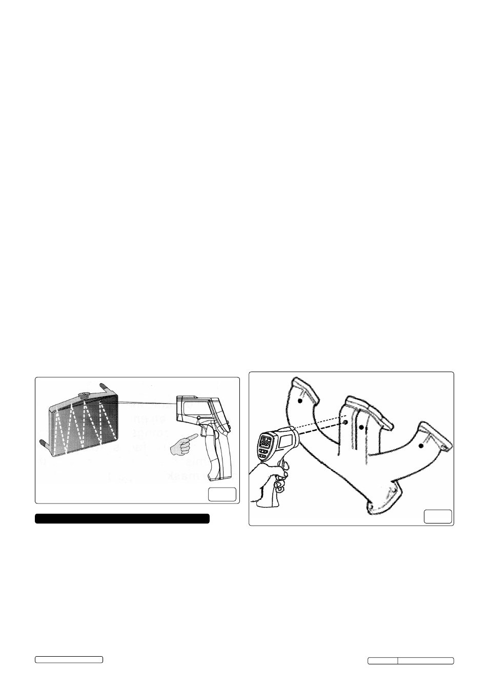
4.6. Locating a Hot Spot (fig.5)
4.6.1.
to find a hot spot aim the thermometer outside the area of
interest, then scan across with an up and down motion until you
locate a hot spot.
Original Language Version
© Jack sealey Limited 2012
WARNING! When working on vehicle systems, take all the
precautions necessary to ensure the safety of yourself and
others - always refer to vehicle manufacturer’s handbook/
service manual. The purpose of this tool dictates that it will be
used close to very hot equipment and therefore extreme care
should be exercised.
5.1. Air Conditioning
5.1.1. With the air conditioning set to maximum cooling, the
temperature of the output air should be at least 15°c colder
than the outside ambient once the system has stabilised.
DO
NOT place the thermometer directly in the cold air stream
(thermal shock) but rather hold it to one side and take the
temperature of the air duct. If the air temperature differential is
less than 15°c have the A/c system checked.
5.2. Heater
5.2.1. With the engine running, and at normal operating temperature,
A/c ‘off’ and heater controls ‘on’ measure the temperatures
of the heater inlet and outlet hoses/pipes at the engine
compartment bulkhead. the outlet hose/pipe should be
approximately 10°c cooler than the inlet. If the differential
is significantly more than this the flow through the heater core is
restricted and the system should be investigated.
5.3. Radiator
5.3.1. When the engine is running at normal operating temperature,
there should be an even temperature drop between the radiator
inlet and outlet. check the whole radiator surface for any ‘cold’
spots which would indicate a blockage.
5.4. Thermostat
5.4.1. under normal operation the thermostat will open as the
engine reaches operating temperature, releasing hot coolant
into the hose linking the thermostat housing to the radiator.
5.4.2. use the thermometer to monitor the hose temperature,
adjacent to the thermostat housing, as the engine warms up to
operating temperature (85°c-105°c).
5.4.3. If the hose temperature abruptly and quickly increases, the
thermostat is functioning correctly.
5.4.4. If the temperature increases gradually and does not reach
operating level, the thermostat has failed in the open condition
(or is missing).
5.4.5. If the temperature does not rise at all the thermostat has failed
in the closed condition or coolant is not flowing for some other
reason (air lock, pump failure etc.) and further investigation is
required.
5.4.6. A fluctuating temperature indicates a weak thermostat spring or
air in the system.
5.5. Misfiring Cylinder (fig.6)
5.5.1. A misfiring cylinder (petrol or diesel) can be located by taking
temperature readings of each branch of the exhaust manifold.
5.5.2.the cool branch will indicate the misfiring cylinder. the
temperature difference will be most marked before the engine
has warmed up and heat transfer has heated the cool branch.
5.5.3. one exhaust branch hotter than the rest (petrol) suggests weak
mixture to that cylinder, which should be investigated (faulty
injector, inlet manifold gasket leak, etc.).
fig.6
5.6. Catalytic Converter
5.6.1. With the engine at normal operating temperature and running
at 1000rpm the inlet of the catalytic converter should be cooler
than the outlet by >55°c (2-way converter) or >20°c (3-way
converter).
5.6.2. If the outlet temperature is lower than the inlet then the
converter is ‘plugged’ and must be replaced.
5.6.3. If the outlet temperature is the same as the inlet then the
converter has reached the end of its service life (say 150,000
miles) or the converter material has broken up due to damage
or has become contaminated.
5.6.4. Always determine the cause of failure, and rectify if appropriate,
before fitting a replacement.
Original Language Version
Original Language Version
Vs907 Issue: 2 (sP) - 22/07/13