Fig.2 fig.3, Fig.4, Operation – Sealey VS907 User Manual
Page 2
4. OPERATION
3.2. LCD Display (fig.2)
A - temperature reading.
B - temperature unit of Measurement indicator
c - Laser on icon
D - Backlight on icon
E - Battery status icon
f - scanning icon
G - Data Hold icon
H - Mode/Emissivity indicator
I - Data storage/read icon
J - Low temperature Alarm icon
K - High temperature Alarm icon
L - set/record Value Indicator
3.3. Buttons and Controls (fig.3)
1 - Trigger. Press to switch thermometer on. Press and hold to
scan. the temperature reading (fig.2-A) and the scanning
icon (fig.2-f) will show on the LcD display. When the trigger is
released, the last recorded temperature reading (fig.2-A) and
the Data Hold icon (fig.2-G) will show.
Note! the thermometer will automatically switch off when not
used for 30 seconds.
2 - Laser/Backlight Button. Press to operate the laser and
the backlight. When the laser is on, the Laser on icon will
show (fig.2-c). When the backlight is on, the Backlight on icon
will show (fig.2-D). the backlight will only operate continually
for 10 seconds.
3 - MODE Button. Press to navigate the mode menu. When
the required mode is reached, press the sEt button (4) to
enter.
MAX mode - will display the maximum temperature measured
on the set/record Value Indicator (fig.2-L) during a single
scan.
MIN mode - will display the minimum temperature measured
on the set/record Value Indicator (fig.2-L) during a single
scan.
DIF mode - will display the difference between the highest and
lowest measurements on the set/record Value Indicator
(fig.2-L) during a single scan when the sEt button (4) is
pressed.
AVE mode - will display the average reading measured on the
set/record Value Indicator (fig.2-L) during a single scan.
HAL - High temperature Alarm. use the arrow buttons (5) to
set a high temperature alarm reading on the set/record Value
Indicator (fig.2-L) and enter using the sEt button (4). When
the pre-set temperature is exceeded during scanning, HIGH
will show on the LcD display (fig.2-K) and the audio alarm will
sound.
LAL - Low temperature Alarm. use the arrow buttons (5) to
set a low temperature alarm reading on the set/record Value
Indicator (fig.2-L) and enter using the sEt button (4). When
the pre-set temperature is exceeded during scanning, LoW will
show on the LcD display (fig.2-J) and the audio alarm will
sound.
STO - Data storage. Press the sto button (6) and then the
sEt button (4), the data storage/read icon (fig.2-I) will show
on the LcD display and 1--- will show in the set/record Value
Indicator (fig.2-L). to store the reading, press the sto button
(6) and the set/record Value Indicator (fig.2-L) will show 2---,
ready for the next reading to be stored. there are 12 groups
available in the thermometer memory. Data can be recalled in
normal measuring mode by pressing the sto button (6). to
clear the memory press and hold the sto button (6) for 3
seconds.
EMS - Emissivity set-up mode. use the arrow buttons (5) to
alter the emissivity setting displayed in the set/record Value
Indicator (fig.2-L). Press the sEt button (4) to confirm
selection. the default setting for EMs is 0.95.
4 - SET Button. this button is used to confirm mode selection
or any settings made.
5 - Arrow Buttons. these buttons are used to alter settings
in the HAL/LAL/EMs modes.
6 - STO Button. this button is used for various functions in the
data storage mode.
7 - Temperature Unit Switch. Located in the battery
compartment area in the handle, this switch converts between
°c and °f.
Original Language Version
© Jack sealey Limited 2012
fig.2
fig.3
4.1. How the Unit Functions
4.4.1. the infrared thermometer measures the surface temperature
of an object. the unit’s optics sense emitted, reflected and
transmitted energy which is collected and focused onto a
detector. the unit’s electronics translate the information into a
temperature reading which appears on the LcD display. the
laser is for aiming purposes only and plays no part in the
temperature measurement.
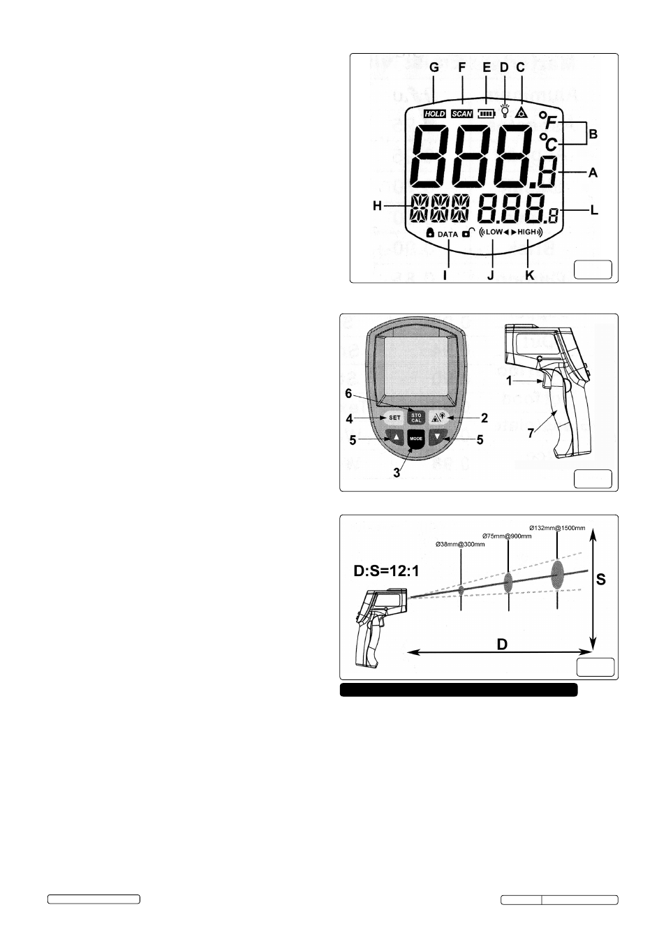
4.2. Field of View (fig.4)
4.2.1. the units field of view is 12:1. this means that if the unit is
positioned 300mm from the target the diameter of the
object under test must be at least 38mm. As a general rule
make sure that the target is larger than the relevant spot size.
the smaller the spot size the closer you should be to the
target. When accuracy is critical, make sure that the target is
twice as large as the spot size.
fig.4
Original Language Version
Vs907 Issue: 2 (sP) - 22/07/13