Fig.3 fig.4 fig.2 – Sealey TP200 User Manual
Page 3
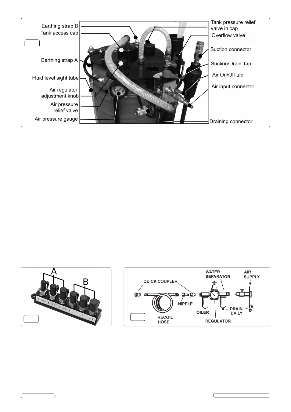
4.7.
Set the controls for suction.
4.7.1.
Turn the Suction/Drain tap (fig.2) to the SUCTIOn position.
4.8.
Starting the pump suction. The pump is controlled by the regulator associated with the incoming workshop air supply or supply
from a portable compressor. Set the air pressure on the incoming supply to between 70 and 100psi. Higher pressures provide no
benefit and may impair or damage the pump.
Do not completely open the valve or run the pump at its maximum speed. To start
the pump open the air on/off tap on the unit (fig.2).
4.9.
Turn the pump off by closing the air on/off tap after all the fuel has been transferred.
Turn the pump off as soon as possible after the fuel is extracted as prolonged free running may damage the pump.
4.10.
Unless the fuel is to be returned to the vehicle immediately, it should be stored in a designated lockable, well-ventilated area,
preferably outside the workshop.
4.11.
Any contaminated fuel or petrol/diesel mixtures should be consigned to waste, giving a clear description of the nature of the material.
4.3.4.
Ensure the main hose is connected to the air pump as shown in fig.1.
4.3.5.
Disconnect the carburettor’s fuel inlet pipe and push it onto the fuel line adaptor.
4.4.
Fuel-injected vehicles. Fuel can be transferred from fuel-injected vehicles through the injector’s fuel inlet pipe.
4.4.1.
Use connector type ‘B’ (fig.1). Choose the required diameter.
4.4.2.
Screw the adaptor and washer into the quick coupling adaptor (fig.1) and then the adaptor hose.
4.4.3.
Plug the male fitting on the other end of the adaptor hose into the quick connector main hose (fig.1).
4.4.4.
Plug the male fitting on the other end of the main hose into the quick connector on the end of the filter (fig.1).
4.4.5.
Disconnect the vehicle’s fuel inlet pipe coming from the tank and slide the ‘banjo’ fitting onto the adaptor.
4.4.6.
Use the two gaskets from the ring removed from the car to obtain a good seal.
4.5.
Transferring fuel directly from the tank.
4.5.1.
Connect one of the three probes to the filter as shown in fig.1.
4.5.2.
Access to the tank may be gained from the boot through a porthole, closed by a guard or a safety device, if the vehicle is fitted with
an anti-theft device at the fuel tank inlet. Remove the guard, and the relevant cap and insert the probe into the hole. This will allow
quicker transfer of fuel than the previous two methods.
4.5.3.
In older vehicles, the probe can be inserted directly into the fuel tank through the fuel tank inlet.
4.6.
Connect the workshop air supply. Recommended hook-up procedure is shown in fig.4 below.
4.6.1.
Ensure the air inlet tap is OFF before connecting to the air supply.
4.6.2.
You will require an air pressure of 72 -100psi, and an air flow of 12cfm.
4.6.3.
WARNING! Ensure the air supply is clean and does not exceed 100psi while operating the drainer. Too high an air pressure and
unclean air will shorten the product life due to excessive wear, and may be dangerous causing damage and/or personal injury.
4.6.4.
Drain the air tank daily. Water in the air line will damage the air motor.
4.6.5.
Clean air inlet filter weekly.
4.6.6.
Line pressure should be increased to compensate for unusually long air hoses (over 8 metres). The minimum hose diameter should
be 1/4” I.D. and fittings must have the same inside dimensions.
4.6.7.
Keep hose away from heat, oil and sharp edges. Check hoses for wear, and make certain that all connections are secure.
fig.3
fig.4
fig.2
Original Language Version
TP200.V3 (C) Issue: 2 - 09/08/12
© Jack Sealey Limited