Conical expanding adaptors – Sealey VS0033 User Manual
Page 2
NOTE: It is our policy to continually improve products and as such we reserve the right to alter data, specifications and component parts without prior notice.
IMPORTANT: No liability is accepted for incorrect use of this product.
WARRANTY: Guarantee is 12 months from purchase date, proof of which will be required for any claim.
INFORMATION: For a copy of our latest catalogue and promotions call us on 01284 757525 and leave your full name and address, including postcode.
01284 757500
01284 703534
Sole UK Distributor, Sealey Group,
Kempson Way, Suffolk Business
Park
, Bury St. Edmunds, Suffolk,
IP32 7AR
www.sealey.co.uk
W e b
Original Language Version
VS0033 Issue: 1 - 25/09/12
© Jack Sealey Limited
6. MAINTENANCE
6.1
Always keep the rubber cones clean and free of oil and grease. Clean them regularly with a non-aggressive cleaner,
ensuring dry before storage.
6.2
In order to preserve elasticity, do not expose rubber cones to sunlight over an extended period of time.
5.1
Follow the manufacturer's instructions for removal of filler cap, use a damp cloth or gloves and arm protection if
the system is known to be hot and or under pressure.
5.2
Select the correct adaptor by first measuring or gauging by eye the filler neck diameter.
5.3
Ensure the sealing conical nozzle is in its "relaxed" condition by visually inspecting the hand wheel incremental cam
lobes. The gap between handwheels will be at their closest.
5.4 Insert the conical nozzle end of adaptor and ensure a partial seal.
5.5 Adjust seal compression integrity by gripping the handwheel nearest the nozzle and rotating the top handwheel clockwise
until an adequate seal is obtained. Resistance will increase with seal compression via the incremental cam lobes.
5.6 Attach the quick coupler of the pump hose on to the conical adaptor.
NOTE!
Due to the design of the internal pump seal, a vigorous pumping action is required to activate the seal and
pressurise the system. A light or slow pumping action will prove ineffective. The larger the air space within the cooling
system being tested, the more vigorous the initial pumping should be. By filling the cooling system and therefore reducing
the airspace within, less effort will be needed to pressurise it.
5.7
Pump the system until the pressure gauge indicates approximately 15 psi.
5.8
If gauge pointer remains stationary for one minute it will indicate that the cooling system is in good working order.
5.9
If the pointer falls, it indicates that the system has a leak resulting in loss of pressure.
5.10
Check the system for water leaks and, if located, repair accordingly.
5.11
If there is pressure loss but no external water leakage check condition of the head gasket.
5.12
Re-test to ensure the repaired system is in good working order.
5.13
Once the test is complete, release the air pressure by depressing the spring loaded pressure relief valve.
5.14
Disconnect the quick coupler.
5.15 Remove the conical adaptor assembly by firstly gripping the handwheel nearest the nozzle and secondly relaxing the seal
compression by rotating the top handwheel counter clockwise fully up to mechanical stop.
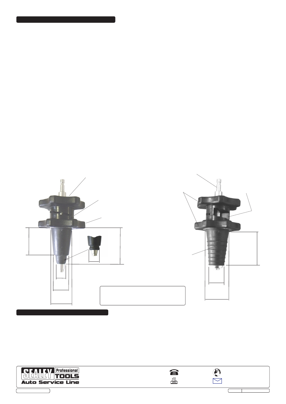
5. OPERATION AND SPECIFICATION
ØA
ØB
C max relaxed C min expanded
Ш17
Ш37
64 max relaxed 54 min expanded
Ø28
Turn handwheel clockwise to
expand rubber cone to seal tight.
Incremental compression
cam lobes (shown in fully
relaxed position)
Grip handwheel whilst
expanding rubber cones.
Part No
VS0033.01 (only)
Part Nos
VS0033.02
VS0033.03
VS0033.04
Model "A" min "A"max "B" "C"max "C"min
VS0033.02 28 31.5 41 74.5 64
VS0033.03 37 39.5 50 74.5 64
VS0033.04 47 48.5 60 74.5 64
Ø24
Expanded fully
Male connector
Rigid plastic (POM)
handwheels
Flexible rubber nozzle
Conical expanding adaptors
46
Incremental compression
cam lobes (shown in fully
expanded position)