Sealey SM100 User Manual
Page 2
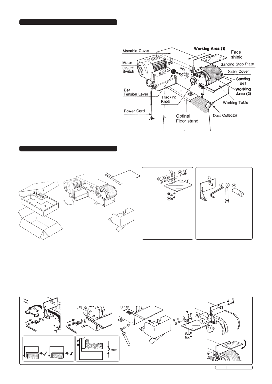
3.1. package content
unpack carton as illustrated below and identify each part according to item description. should there be any damaged or missing parts contact
your supplier immediately.
3. paCkaGe Content & asseMblY
2. desCrIptIon & speCIFICatIons
motor . . . . . . . . . . . . . . . . . . . . . . . . . . 0.75kW 1Hp
Power . . . . . . . . . . . . . . . . . . . . . . . . . . 230V - 1ph
sanding belt . . . . . . . . . . . . . . . . . . . . . 100 x 1220mm
Belt speed . . . . . . . . . . . . . . . . . . . . . . 19m/sec (50Hz)
driving wheel . . . . . . . . . . . . . . . . . . . . Ø 126 x 105mm
flat grinding surface. . . . . . . . . . . . . . . 320 x 105mm
dimensions (lxWxH) . . . . . . . . . . . . . . 650x380x260mm
Weight . . . . . . . . . . . . . . . . . . . . . . . . . 27.5kg
“A” weighted sound . . . . . . . . . . . . . . . 82.0 dB
“B” weighted sound . . . . . . . . . . . . . . . 81.6 dB
the sm100 has a heavy cast base with adjustable sanding table. fitted with magnetic no-volt release switch to prevent accidental starting
should the belt jam. equipped with a quiet and powerful 230V 1Hp motor, the sm100 is suitable for metal and fabrication workshops.
An optional floor stand is available.
optional stand part number sM100/st specifications:
machine height (with stand) . . . . . . . . . 1070mm
cabinet stand size (lxWxH). . . . . . . . . 380x395x810mm
spare belts available as follows:
sm100/B080G
80 grit sanding belt
sm100/B100G
100 grit sanding belt
no description
Qty
1
face shield
1
2
support plate
1
3
Hex bolt 1/4” x 1/2”l
1
4
Washer m6 x18x2
1
5
spring washer 1/4”
1
6
Wing nut 1/4”
1
7
screw 3/16 x 7/16”l
2
8
Washer 3/16”x12x0.8
2
9
Hex nut 3/16”
2
Item 1
Main body
Carton
with item identification
no description
Qty
1
sanding stop plate
1
2
6mm Hex wrench
1
3
12mm open spanner
1
4
socket wrench
1
Item 5
dust cover
Item 2
work table
Item 4
sanding stop plate & tools
Item 3
Face
shield
3.2
asseMblY
warnInG! ensure sander has not been connected to mains power supply. refer to diagrams to assist assembly.
3.2.1 tensIon and sandInG stop plate
the belt tension has been pre-set by the manufacturer. for shipping purposes the manufacturer has slackened the tension by turning
the tension lever to the “loosen” position. to re-tension the belt push the lever down toward the “tighten” position (fig 1). install the
sanding stop plate and ensure that it does not touch the sanding belt see fig 1 & 1a.
3.2.2 workInG table
locate working table in correct position (fig 2) ensure the distance between the working table and the sanding belt is at 3mm (fig 2a).
3.2.3 dUst ColleCtor
fit the dust collector unit with washer and bolt on each side (fig 3).
3.2.4 saFetY FaCe sHIeld
install the face shield and make adjustments to gain the maximum protection (fig 4 & 5).
fig 2
fig 3
fig 4
fig 5
fig 1a
fig 2a
fig 1
Original Language Version
sm100 issue: 2 - 23/11/09