Fig.6 fig.7 fig.8 – Sealey SMS2003 User Manual
Page 4
4.8.
SAW bLADES WITH SET TEETH
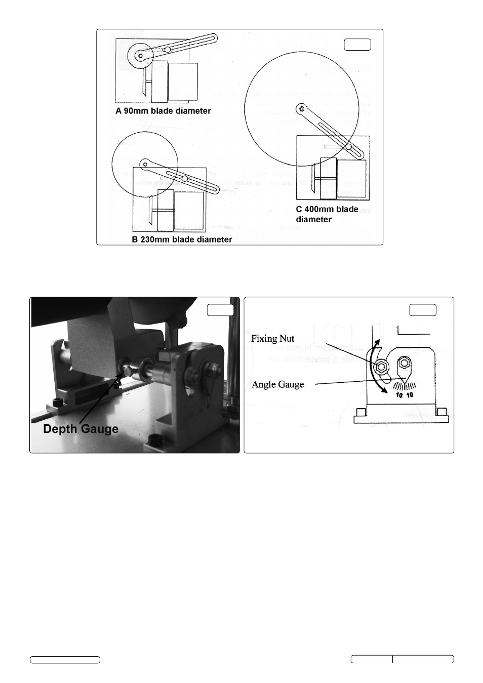
4.8.1 For saw blades with set teeth the motor can be tilted. Unscrew the fixing nuts on both sides of the motor retainer and adjust to the desired
angle. The motor can be tilted up to 25° in both directions. (See fig.8). It might be possible that the desired angle cannot be reached as
the motor touches the base plate for large angles. In this case turn the motor block by 180° within the collar of the motor holder (loosen
the clamping screw, (see fig.1) on the neck of the motor). (See fig.8).
4.9.
SHARPENING OF CIRCULAR SAW bLADES
4.9.1. After all the adjustments have been completed, position the locking pin in such a way, that it will put slight pressure on the saw blade
. (See
fig.9).
4.9.2. Switch the machine on to start the sharpening process and operate the lever to move the grinding stone towards the tooth until it has
reached the adjusted depth gauge.
4.9.3. Pull back the grinding stone (by the operating lever) and turn the saw blade to sharpen the next tooth. Repeat these steps until all teeth
have been sharpened.
NOTE: In case of set teeth, only grind every second tooth and then reverse the angle to grind the remaining teeth.
4.9.4. When grinding the tooth back make sure the grinding stone and saw blade are orientated as shown in fig.3.
Original Language Version
© Jack Sealey Limited
SMS2003 Issue: 1 27/02/14
4.7.
SAW bLADE SUPPORT
4.7.1. For better stability and more accurate positioning, it is necessary to place the saw blade support as close as possible to the grinding stone,
so that the saw blade can rest on it. (See fig.1).
4.6.
DEPTH GAUGE
4.6.1. After adjusting the correct position of the arm, motor and saw blade, the depth gauge needs to be adjusted.
4.6.2. To adjust the depth gauge, position the grinding stone into the tooth bottom, so that the tooth face can be completely sharpened, but the
grinding stone does not touch the tooth bottom (there must be a space of some mm). Tighten the fastening screw of the depth gauge to
fix the correct position. (See fig.7).
Fig.6
Fig.7
Fig.8