Fig.2 fig.1 fig. 6 – Sealey GDM200F/VS User Manual
Page 3
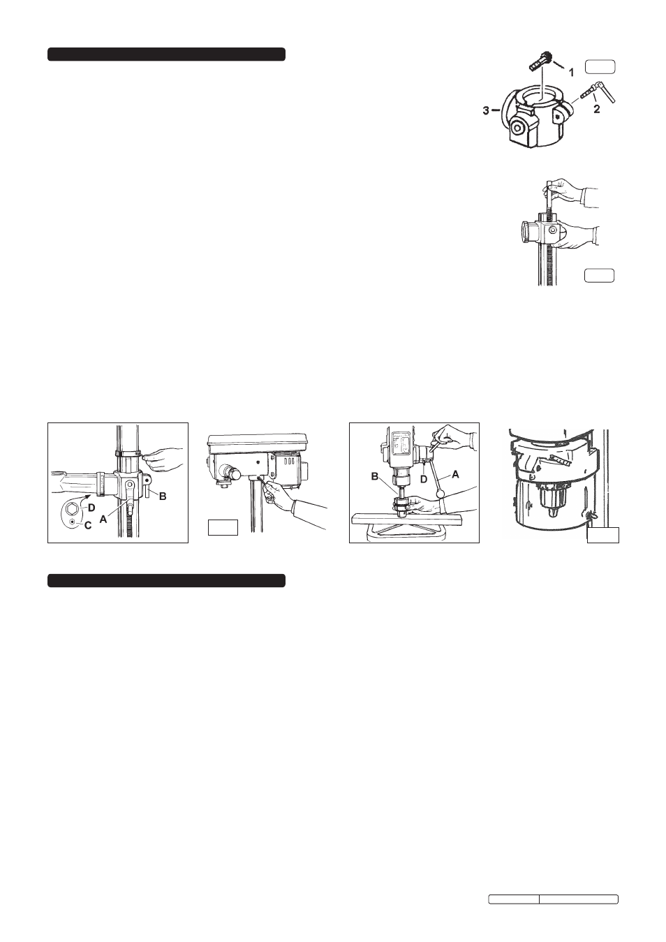
WARNING! Ensure that the drill is unplugged from the mains power supply before commencing.
6.1. Installing drill bit
6.1.1. Insert drill bit into chuck jaws to 1" (25mm) deep (avoid inserting small bits too far) and centre bit in chuck before tightening.
6.2. Adjusting the table
6.2.1. to adjust table up or down, loosen lock handle (fig.3.B), then turn bracket handle (fig.3.A). once at correct height tighten lock handle.
6.2.2. to adjust table tilt, remove the locating pin and nut (fig.3.c) - if pin is tight, turn nut clockwise to loosen. Loosen the table arm bolt
(fig.3.D), adjust table to the desired angle using the angle scale, then retighten the table arm bolt. When the table is returned to the
horizontal, replace the locating pin and nut.
6.2.3. to turn the table around the column, loosen the lock handle. turn the table to the desired position and then tighten the lock handle.
6.3. Adjusting the speed
6.3.1. Determine the speed for the drilling operation (see drill speed chart) and, with the motor running, move the speed control handle (turn
anticlockwise to loosen) to that speed as marked on the pulley housing. Lock the lever in position by turning it clockwise and turn off
the motor.
6.4.
Positioning the workpiece
6.4.1. rest the workpiece on a piece of wood to prevent the drill bit damaging the table when it breaks through.
the wood should rest on the table so that one end of it is against the left side of the column. When the drill bit breaks through the
workpiece, it will contact the wood and cause it to spin. resting the wood against the column will help prevent this.
6.4.2. for small workpieces that cannot be clamped to the table, use a drill vice (not included). Vice must be clamped or bolted to table.
6.5.
Setting the drill depth
6.5.1. use the scale on the side of the drill head near the drill handle.
6.5.2. Loosen locking screw (fig.5.D) and set the scale to the depth required. tighten locking screw.
6.5.3. When ready to drill, simply pull the feed handle. the drill will stop at the set depth.
6. OPERATING INSTRUCTIONS
5. ASSEMBLY
fig. 3
fig. 4
fig. 5
note: figures are illustrative and may differ in detail from your drill.
5.1. Assembly
5.1.1. Place the column assembly on the base, align holes and secure with the four bolts provided.
5.1.2. Insert the worm gear (fig.1.1) into the table bracket crank handle hole, ensuring that the worm
gear meshes with the rack gear in the bracket.
5.1.3. screw the lock handle (fig.1.2) into the lugs at the rear of the table bracket but Do not tighten.
5.1.4. Install the table bracket onto the column together with the rack (fig.2), engaging gear in bracket with
rack teeth. note that the rack should be assembled with the longer tooth-free end uppermost.
5.1.5. Install the rack collar and tighten grub screw firmly (fig.3). Ensure that rack is free to move around column.
5.1.6. Install the table adjusting handle (fig.3.A) onto the worm gear shaft, tightening the grub screw onto the flat on the shaft.
5.1.7. tighten the table bracket lock handle (fig.3.B).
5.1.8. fit the table arm to the table bracket with the bolt and washer provided (fig.2.D).
5.1.9. fit the table to the table arm and clamp in position with the smaller lock handle.
5.1.10. carefully place the head assembly over the column and slide it into position. Align head with base.
5.1.11. fit the two set screws in the side of the head to lock it into position and tighten with hex. key (fig.4).
5.1.12. screw the three feed handles and knobs to the hub of the pinion shaft (fig.5.A).
5.1.13. open the pulley cover and then insert the speed control handle through the side of the pulley housing.
screw the handle into the central pulley carrier with the flats on the outer sleeve of the handle engaged
in the guide slot.
5.1.14. to install chuck open the chuck jaws completely by turning the chuck key counter-clockwise. Place a piece
of wood on the drill table (to prevent the chuck from getting damaged).
5.1.15. Insert larger tapered end of arbor (fig.5.B) into drill spindle - rotate slightly to engage fully, fit chuck to protruding end of arbor and hold
in place.
5.1.16. turn feed handles to bring nose of chuck down onto wood (fig.5). firmly pull on feed handle to seat arbor taper in spindle and chuck.
5.1.17. Loosen clamp screw on safety guard mounting collar, pass guard up over chuck and fit collar round flange of quill shaft. Ensure guard
pivot is central and tighten clamp screw (see fig.6).
5.2. Drill mounting
5.2.1. for stability and safety it is important that the drill base is securely bolted to the workbench (GDM150B/Vs) or floor (GDM200f/Vs).
5.2.2. Ensure that the mounting surface is capable of supporting the drill together with the weight of the heaviest likely workpiece.
fig.2
fig.1
fig. 6
Original Language Version
GDM200f-Vs Issue no.1 27/02/12