Operation – Sealey AVR2500A User Manual
Page 4
5.6.
Operating the pump (fig.6)
5.6.1. Elevate by depressing the pump pedal position "A" and hold.
5.6.2. Park the lift at any pawl prop notched height by removing the foot from the pump with a bias toward position "B". See fig.7 and
note 5.8.7.
5.6.3. control descent by briefly depressing the pump pedal position "A", to enable pawl prop disengagement, followed by fully depressing
pump pedal position "B", depressing valve "c" and hold.
See fig.6.
5.7.
Test run
5.7.1. Before each use, check the vehicle lift is functioning correctly and ensure it is not damaged or worn.
5.7.2. With the air line connected operate the lift valve pedal to trial elevate, release the valve to stop. Lower the lift by operating the
hydraulic release valve pedal. It will only elevate or descend whilst the pedal is being operated ("Operater present" system).
5.8.
Lifting the vehicle
5.8.1. Lock, chock and handbrake vehicle wheels as required. Remove any objects left on the boot lid, bonnet and roof.
5.8.2. The vehicle lift assembly is mounted on two sprung loaded castors at one end for transit. Manouevrability is obtained by inserting the
pin of the twin wheeled carriage, as shown in fig.1 at the opposite end. Partially elevate the frame with the twin wheeled carriage lever
and position beneath the vehicle as shown in fig.2 and fig.3.
5.8.3 Remove the two compression springs by elevating the frame with the twin wheeled carriage lever at the sprung loaded castor end.
This will remove the compression spring forces, allowing removal from the castor bracket and placing them into the retaining cups.
5.8.4. With the fully lowered frame centrally positioned beneath the vehicle, locate the support pads on to their respective swivel arms and
decide on safe and mechanically stable areas for lift.
5.8.5. "Inch" elevate the lift with the foot pedal and rotate the pads anticlockwise to contact the vehicle, ensuring the pin enters a graduated
pin hole in the quadrant plate of the swivel arm (fig.4). This will prevent unexpected movement of the load.
5.8.6. With the air line connected, operate the lift valve pedal to trial elevate, release the valve to stop if required.
5.8.7. continue to elevate, observing the pivotting pawl props. notches in the base frame govern fixed height "parking stations". The first
"parking station" represents an elevated height of 500mm; although distances vary between notches they each represent a 100mm
graduated step in elevated lift. Release the pump foot pedal at the required "parking station" notch, and allow both prop arms to
engage with the notch (fig.7). Lower the lift by operating the hydraulic release valve pedal, until the prop engages with the notch edge.
5.8.8. Lower the lift by operating the foot pedal; this action operates a 3 port 2 position pneumatic valve. Two small pneumatic cylinders in
the area of the pump utility tray, rotate the pawl prop guide rails, lifting the props out of the "parking station" notches. See fig.7, fig.4
and pneumatic circuit fig.8. Control descent by briefly depressing the pump pedal position "A" (fig.6), to enable pawl prop
disengagement, followed by fully depressing pump pedal position "B"(fig.6), depressing valve "C"(fig.6) and hold.
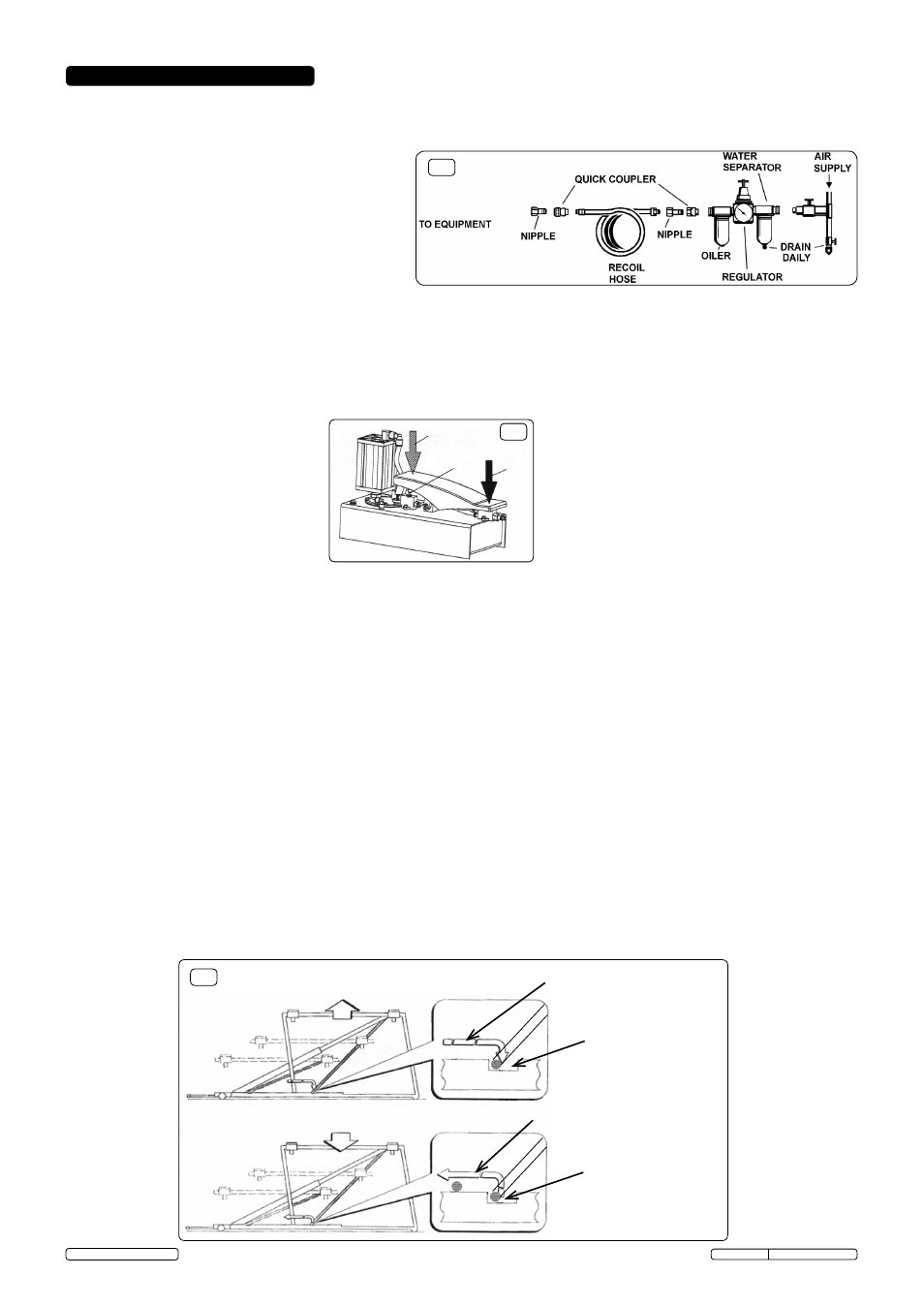
5.1.
Ensure the air supply valve is in the "Off" position (fig.5) before connecting to the air supply. The air/hydraulic lift requires a minimum
air pressure of 6-7bar to operate. Mains air supply, suggested minimums, 200ltr compressor and 1/2" pipework.
WARNING! Ensure the air supply is clean and does not exceed 7bar). Too high an air pressure and unclean air will
shorten the life of the unit due to excessive wear, and may be dangerous causing possible damage and/or personal injury.
5.2.
drain the air supply tank daily and clean the air
inlet filter screen weekly.
5.3.
For recommended supply, see diagram (fig.5) to right.
5.4.
Line pressure should be increased to compensate for
unusually long air hoses (over 8 metres).
5.5.
Keep hose away from heat, oil and sharp edges.
check hoses for wear and make certain that all
connections are secure.
WARNING! In an emergency, if a shut off valve is
not available in the mains air supply line, disconnection of the air line from the pump would achieve the same result.
5. OpERATION
fig.7
"A"
"B"
"c"
fig.6
Path of pawl follower
Path of pawl follower
Engagement with
"parking station" notch
disengagement with
"parking station" notch
Ascending
descending
"Operater present" pump
Original Language Version
AVR2500A Issue: 1 - 07/11/14
© Jack Sealey Limited
fig.5
SHUT OFF
VALVE