Fig.2 – Sealey AVR1500FP User Manual
Page 2
Original Language Version
AVR1500FP Issue: 1 - 15/04/13
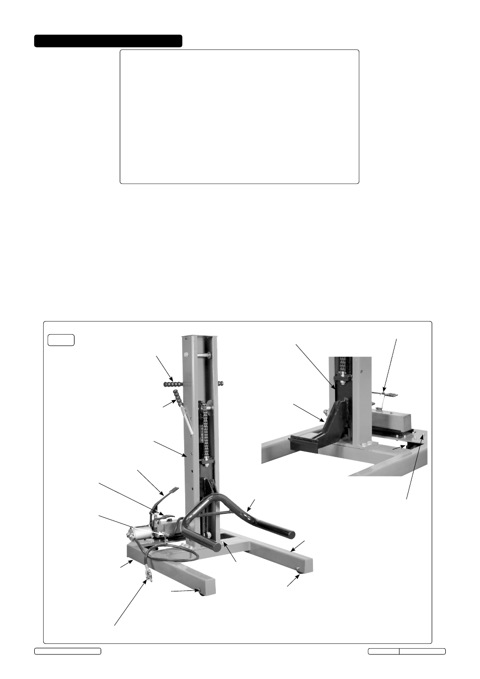
4. PARTS AND ASSEMbLY
Item Description
Qty
1
Vertical pillar assy c/w elevator carriage and hydraulic connector hose 1
2
Base frame assy c/w air line connection and hydraulic system
1
3
Swivel castors
2
4
Fixed roller castors
2
5
Roller spindles Ø16
2
6
Circlips Ø16
4
7
Wheel cradle adaptor
1
8
Body lift adaptor
1
9
Stop bar
1
10
Handle grips Ø15
3
11
Hexagon screw M12
6
12
Hexagon nut M12
6
13
Plain washer Ø12
6
14
Socket head cap screws M6
8
15
Hexagon nut M6
8
16
Plain washer Ø6
8
1
2
4
3
5,6
7
9,10
11,12,13
10
Air line connection on/off valve
Pump foot pedal
Back to tank
release valve pedal
Hydraulic hose
connection
4.1
Assembly
4.1.1 Remove contents from packaging and display contents
. Check with above list and in the unlikely event of missing or
damaged parts contact your Sealey dealer immediately. Some components are pre-assembled, in particular (items 1
and 2).
4.1.2 If not pre-assembled fit castors (item 3) to base frame (item 2) with fixings (items 14,15 and 16). Also roller castors
(item 4) with spindles (item 5) and retain with circlips (item 6). The base frame needs to be supported and on an edge
in this process.
4.1.3 With assistance, bolt the vertical pillar (item 1) to base frame (item 2). It will be necessary to do this with the vertical
pillar horizontal and the base frame on an edge. Tighten the fixings (items 11,12 and 13) to a minimum torque of 60NM.
4.1.4 Stand the unit upright on a flat level surface and connect the hydraulic hose from the vertical pillar to the pump as
shown in (fig.2).
4.1.5 Place the stop bar (item 9) with grip fitted (item 10) into its sleeve on the vertical pillar. Fit the other two grips to the
handlebars also on the pillar.
4.1.6 Release the foot pump pedal from the transit hook.
4.1.7 Adaptors (items 7 and 8) hook on and hook off the duplex chain lift carriage as and when required.
8
14,15,16
Transit hook
Elevator carriage
Fig.2
3
© Jack Sealey Limited 2013