Fig.4 fig.5, Installation, Operating instructions – Sealey PW1360 User Manual
Page 3
Original Language Version
© Jack sealey Limited
3. INSTALLATION
3.1
BALL HITCH MOUNTINg INSTRUCTIONS
3.1.1 If using the ball hitch mounting plate ensure that the mounting area has sufficient strength to support a load well in excess of the
rated winch capacity.
3.1.2 slide the mounting plate on to the bottom of the winch and pass it over the ball hitch.
3.2
FIXED MOUNTINg INSTRUCTIONS
3.2.1 Ensure that the mounting surface is of sufficient strength to support a load well in excess of the rated winch capacity.
3.2.2 fasten the winch to the mounting surface with three 13mm bolts, washers and lockwashers. Position the winch so that the cable does
not rub the front opening of the winch.
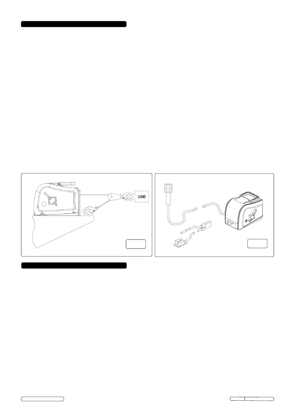
3.2.3 for double line use, install an eye hook on the winch stand close to the base of the winch for fastening the stationary cable hook, see
fig.4. Be sure that the eye hook is of sufficient strength to withstand loads in excess of the single line rating of the winch.
3.2.4 the winch is equipped with keyhole slots in the base for use with quick mounting shoulder studs. they should be mounted securely into
the winch stand. After positioning the winch on the studs, a 10mm bolt should be placed in one of the other holes available to keep the
winch securely in position.
3.2.5 Make sure that the winch is positioned so that the hook will not be drawn into the drum and the cable will not rub the front opening.
DO
NOT reverse the direction the cable is wound on to the drum.
3.3
WIRINg HARNESS INSTALLATION
3.3.1 the wiring harness is designed to be permanently installed on a vehicle and stored in the boot or truck bed etc. this prevents
tampering, accidental or misuse of the winch, since the harness is required to power it electrically. the wiring harness can be made
removeable from the vehicle with the 'Electrical Quick connect', see parts list for details.
3.3.2 feed the positive lead (long) wire through any convenient access hole in the car boot. (It may be necessary to remove a grommet or
plug). It may also be necessary to remove the circuit breaker assembly from the positive wire in order to feed the wire under the car.
3.3.3 Pull the positive lead wire along the underside of the car into the engine compartment and up to the battery.
3.3.4 fasten the short lead from the circuit breaker to the positive (+) battery terminal, (if it is a nut and bolt type) or to the battery side of the
starter solenoid. use the lugs on the circuit breaker casing to attach it to a safe position.
3.3.5 Attach the negative wire to an earth on the chassis using a 6mm bolt and locknut. Make sure it is a clean, tight connection.
3.3.6 fasten the wiring to the underside of the car using wiring clamps and brackets, or cable ties as needed, making sure that it is not
located near the exhaust or hot or moving parts. Wiring should be fastened securely and without slack. Excess wire should remain in
the boot.
NOTE: If the winch is mounted at the front of the vehicle, cut the harness to the length needed. If spliced, make sure the splice is tight
and well insulated. Attach the earth as described in 3.3.5.
CHECk THE WINCH THOROUgHLY BEFORE OPERATINg!
4. OPERATINg INSTRUCTIONS
WARNINg!
this electric winch should be respected as power equipment. High forces are created when using a winch, creating
potential safety hazards.
DO NOT allow children or anyone not familiar with the operation of the winch to use it.
WARNINg! Inspect the cable before each use, replace it immediately if it is damaged or worn.
WARNINg! the auxillary handle is for emergency use only. DO NOT use the auxillary handle to assist the motor when it is
running. Always remove the auxillary handle when it is not in use.
WARNINg! When releasing a load with the clutch, maintain control of the speed. Excess speed could result in winch damage and
severe personal injury.
4.1 WINCHINg
4.1.1 Connect the power supply plug into the connector on the back of the winch, see fig.6. The plug pushes and snaps into place and
will only fit in one position. Connect the remote switch cable by plugging it in on the back of the winch, see fig.6. Leave the vehicle
engine running at fast idle.
4.1.2 With the clutch lever in the 'engaged' position you can pay out or pay in the cable. Allowing the switch to return to the off position will
automatically stop the winch and lock the load in position.
NOTE: It is normal for smoke to be produced during initial paying out use.
WARNINg! Even though the winch is equipped with circuit breaker overload protection, special care should be taken not to create an
overload. Pay attention to the sound of the winch and the load being pulled. Make certain that the cable tension does not rise suddenly
because of a bind in the load.
WARNINg! the electric motor is designed for intermittant use only. Extended use without cooling off periods will cause overheating
resulting in motor damage. Maximum recommended run time is four minutes.
4.1.3 When winching is complete, secure the load with appropriate tie down straps or chains. When the load is being transported on a trailer
relieve the tension on the winch cable, to avoid damage to the winch and trailer due to high shock when travelling.
Fig.4
Fig.5
PW1360 Issue: 2 - 17/01/14