Fig.2 fig.3, Fig.4, Fig.5 – Sealey 2000ESLE User Manual
Page 2: Assembly 5. operation 6. maintenance
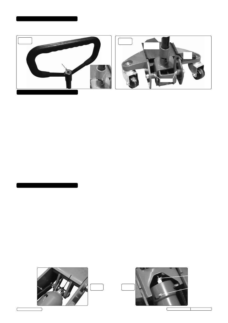
4.1. Place the handle onto the jacking lever tube and fix with supplied M6 X 16 cap screw as shown in fig.2.
4.2. Offer the jacking lever tube into the "L" slotted stub sleeve; look for the tapped hole through the slot as shown in fig.2., fit the
supplied M6 X 35 cap screw.
DO NOT overtighten.
5.1. Before first use.
5.1.1. Before using the jack, purge hydraulic unit in order to eliminate any air in the system. Lift and twist handle as indicated in fig.1, this
opens the valve. Pump by sweeping the handle in fig.1 and fig.2 backwards and forwards for 30 to 40 seconds. When complete, release
the handle and twist to the central position shown in fig.2. This action closes the valve.
5.1.2. Place a few drops of hydraulic jack oil onto the pump cylinder shaft in fig.3 and pump the handle several times to distribute the oil.
Thoroughly lubricate all moving parts.
5.2. General jacking.
p
WARNING! Before lifting ensure Section 1 safety instructions are read and understood.
5.2.1. Prepare the vehicle as mentioned in the safety instructions ensuring the ground on which the jack is to stand is level and solid (not
tarmacadam).
5.2.2. Position the jack saddle under the vehicle manufacturer’s recommended lifting point.
5.3. Jacking the vehicle.
5.3.1. Close the release valve using the handle as shown in fig.2. Commence pumping the foot pedal until the jack saddle reaches the vehicle
jacking point. Sweep the handle up and down using maximum strokes. Check the jacking point is centrally located on the saddle and
raise the vehicle.
5.3.2. Should the jack become overloaded, a safety excess pressure valve will open, and stop the vehicle from lifting.
p
WARNING! The jack is a lifting device only and must not be used to support the load. Use correctly rated axle stands to support the
load.
5.4. Lowering the vehicle
p
WARNING! Ensure there are no persons or obstacles beneath the vehicle, or in the path of its descent.
5.4.1. If using axle stands, raise the jack high enough for the stands to be easily positioned or removed when lowering fully.
5.4.2 Lift and twist the handle slowly to open the valve and lower the vehicle on to the stands.
5.4.3 When lowering fully loaded, the lowering speed is controlled automatically to avoid any sudden changes in descent rate.
fig.2
fig.3
Lubricate
Grease
M6 X 16
Valve
lift and
twist track
6.1. When the jack is not in use, the ram should be in its lowest position to minimise corrosion. Remove the handle to inactivate.
6.2. Keep the jack clean and lubricate all moving parts on a regular basis as in fig.3, fig.4 and fig.5. Smear grease into castor ball journals.
6.3. Before each use check for broken, cracked, bent, or loose parts, or any visible damage to ram, pump, saddle, lifting arm, frame and all
parts including nuts, bolts, pins and other fasteners. If any suspect item is found remove jack from service and take necessary action to
remedy the problem.
DO NOT use the jack if believed to have been subjected to abnormal load or shock load.
6.4. Periodically check the pump piston and the ram for signs of corrosion. Clean exposed areas with a clean oiled cloth.
6.5. After one year the oil should be replaced in order to extend the life of the jack. Use hydraulic jack oil only.
3
I
MPORTANT: Only fully qualified personnel should attempt hydraulic maintenance or repair.
6.6. To check the jack oil level, fully lower the jack. Remove the cover and jack oil filler plug (fig.4). If the jack oil level is low, fill as required.
DO NOT over fill. The correct level is just below the bottom of the plug.
NOTE: Use a good quality jack oil, such as SEALEY HYDRAULIC JACK OIL.
p
WARNING: DO NOT use brake fluid, or any fluid other than hydraulic jack oil as this may cause serious damage to the jack and will
invalidate the warranty!
6.7. When draining the oil make sure that no dirt is allowed to enter the hydraulic system.
3
IMPORTANT: NO RESPONSIBILITY IS ACCEPTED fOR INCORRECT USE Of THIS PRODUCT.
Hydraulic products are only repaired by local service agents. We have service/repair agents in all parts of the UK.
DO NOT return the jack to us. Please telephone us on 01284 757500 to obtain the address and ‘phone number of your local agent. If
the jack is under guarantee, contact your local Sealey dealer.
De-commissioning the Jack
Should the jack become completely unserviceable and require disposal, draw off the oil into an approved container and dispose of the
jack mechanics and the oil according to local authority regulations.
fig.4
Foot
pedal
Lift and twist
assist plunger
(lubricate)
fig.5
Removable
tool tray
Original Language Version
2000ESLE/3000ESLE Issue: 1 - 10/04/14
© Jack Sealey Limited
M6 x 35
Filler plug
Pressure relief
valve
DO NOT
adjust.
Lubricate
cylinder shaft
4. ASSEMBLY
5. OPERATION
6. MAINTENANCE
(Viewed beneath tool tray)
Tension spring