Fig.5, Fig.4, Fig.3 – Sealey SB997 User Manual
Page 2: Preparation, Assembly
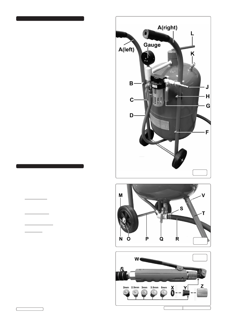
fig.5
fig.4
6. PREPARATION
WARNING! Ensure that you read, understand and apply the
safety instructions in Section 1 before use.
WARNING! Wear approved ear, eye, hand and respiratory
protection when operating the blaster.
WARNING! Ensure the air supply does not exceed 125psi
while operating the unit.
6.1 Control valves.
6.1.1. Air Supply Valve See fig.3G. This valve controls the flow of air
coming into the unit from a compressor or workshop air supply.
When this valve is opened the incoming pressure of air will
register on the gauge and the tank will start to pressurise.
6.1.2. Gun Supply Valve See fig.3C. This valve controls the flow of air
to the sand pick up point at the base of the unit and on to the
blasting gun.
6.1.3. Sand Metering Valve See fig.4Q. This valve controls the
amount of sand flowing down from the tank.
6.1.4. Blasting Gun See fig.5W. This valve opens the flow of sand
from the blasting nozzle and should be either open or shut.
6.2. Abrasives.
There are two types of abrasive grit:
6.2.1. Expendable - Use once and dispose of, recommended for
large surfaces - Copper Slag and Olivene (silica-free sand).
We recommend Sealey Blasting Grit, part number B/25KG
(Use with the 5mm nozzle).
6.2.2. Re-usable - more expensive and recommended for cabinets -
Glass Beads and Fused Alumina.
6.3. Filling the tank with abrasive.
6.3.1. Close the Sand Metering Valve See fig.4Q. Valve lever should
be at right angles to the fitting
WARNING! If an air line is connected ensure the tank is
depressurised by turning off the air supply and operating
the blasting gun until the pressure gauge registers zero.
6.3.2. Undo the tank cap using the attached lever. See fig.3L.
6.3.3 Insert a funnel into the opening.
6.3.4. Fill the tank up to 3/4 full only.
6.3.5. Refit the tank cap ensuring that the 'O' ring seal is in place and
tighten fully.
Original Language Version
fig.3
5. ASSEMBLY
WARNING! Before operating the unit ensure you read,
understand and apply Section 1 Safety Instructions.
5.1 Assembling the handles and wheels.
5.1.1. Place a protective layer on the floor such as cardboard or cloth
and lay the tank down with the water trap and gauge upwards.
Place blocks either side of the tank to prevent it rolling.
5.1.2. There is a specific left hand and a specific right hand handle
as the mounting holes in them are at different angles. When
correctly fitted the two handles should be parallel.
Referring to fig.3, loosely attach the two handles (A) onto the
fixing brackets (B, D, F & H) using the nuts, bolts and
washers provided. Do not tighten yet.
5.1.3 Referring to fig.4, slide the axle (P) through the holes at the
bottom of each handle so that it protrudes equally either side.
Slide a wheel (M) onto each end of the axle followed by a
washer (O). Fix each wheel by sliding a split pin (N) through
the holes in the end of the axle and retain the assembly by
bending over the pins.
5.1.4 Now tighten the nuts and bolts at the four handle mounting
positions. (B, D, F & H in fig.3).
5.2 Assembling the front foot.
5.2.1 Now lay the tank down on its handles and referring to fig.4, fit
the front foot (T) to the spigot welded onto the tank and retain
the assembly by putting the split pin (V) through the foot and
spigot and bending it over.
5.3 Attaching the blasting hose.
5.3.1 Referring to fig.4, take the open end of the blasting hose (R)
and slide the wire screw clamp (S) over the end of it. Now
push the hose fully onto the sand outlet fitting below the sand
metering valve and tighten the wire screw clamp to retain it.
5.4 Fixing / changing the blasting nozzle.
5.4.1 Referring to fig.5, depress and hold the blasting gun handle
(W) to release the seal on the nozzle. Unscrew and remove
the knurled nozzle holder (Z) and release the handle (W).
Push the nozzle (Y) and the 'O' ring (X) out of the holder.
Insert the required nozzle into the back of the holder (Z)
followed by the 'O' ring (X). Depress the blasting gun handle
and screw the knurled nozzle holder back into place.
SB997, SB998 Issue: 4(SP) - 09/02/15
© Jack Sealey Limited