Fig.7 fig.8 – Sealey SM750 User Manual
Page 4
5.7.
Changing the sanding belt.
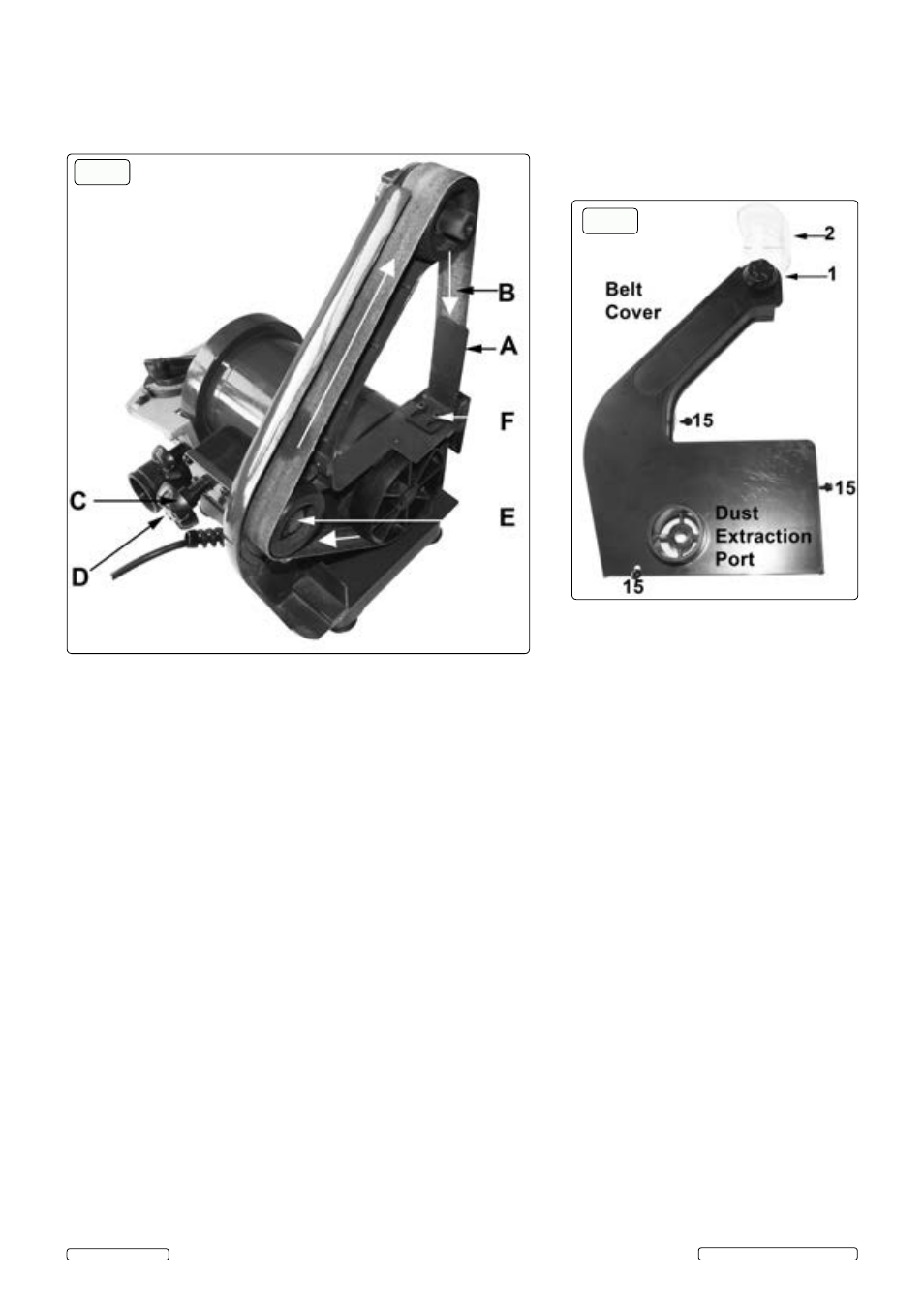
5.7.1. Referring to fig.1 and fig.8, remove the cover clamp knob (1) and lift off the clear protective cover (2).
5.7.2. Referring again to fig.1 and fig.8, remove the three belt cover fixing screws (15) and lift off the black plastic side cover to reveal the belt
and drive wheels as shown in fig.7.
5.7.3. Wheel (E) is spring loaded to hold the belt at the correct tension.
5.7.4. Push the tracking knob (D) forwards against the compression spring to relieve the tension and ease the belt off the drive wheels.
5.7.5. Place the new belt onto the upper and lower wheels. Push knob (D) forwards again and ease the belt back onto wheel (E).
5.7.6. Turn the belt by hand to see if it is running true and make any necessary adjustments using the tracking knob (C) as described in
Section 6.3.1.
5.7.7. Re-fit the black plastic side cover over the belt and drive wheels and fix in place using the two fixing screws.
5.7.8. Refit the clear protective cover (2) and hold it in place with the clamp knob (1).
5.8.
Changing the sanding disc.
5.8.1. The abrasive sanding disc has an adhesive backing in order to attach it to the metal sanding disc.
5.8.2. If fitted, remove the adjustable angle guide from the groove in the sanding table.
5.8.3. Unscrew and remove the two clamp knobs from either side of the sanding disc table. Take hold of the front edge of the disc and pull it
away from the disc to remove it.
5.8.4. Remove the four screws that hold the dust extractor cover in place and put it to one side.
5.8.5. Insert a blade between the back of the abrasive disc and the surface of the metal disc, taking care not to damage the metal surface.
Ease the abrasive disc away from the metal surface until you can get hold of it and then peel it away from the metal disc. Remove any
excess adhesive from the surface of the disc. Peel off the backing from a new abrasive disc and stick it to the metal disc ensuring it is
centred.
5.8.6. Re-attach the exhaust cover and sanding table as described in Sections 5.1 and 5.2.
5.9.
Dust extraction.
5.9.1. Both the belt and the disc are provided with dust extraction ports for connection to a workshop extractor system or a vacuum cleaner
and it is recommended that these facilities be used if they are available.
5.9.2. If no extraction facilities are available you must wear suitable respiratory protection. Contact you local Sealey dealer for a full range of
protective equipment (PPE).
5.6 Attaching the sanding belt backing plate.
5.6.1 Referring to fig.6, position the backing angle behind the belt and insert the two socket head cap screws provided through the slots and
screw them down, finger tight. See fig.7 (F), the angle face should just touch the back of the belt without applying any pressure to it.
5.6.2. Finally tighten the two screws with a 3mm hex key.
fig.7
fig.8
© Jack Sealey Limited
Original Language Version
SM750.V2 Issue No.1 - 08/06/15