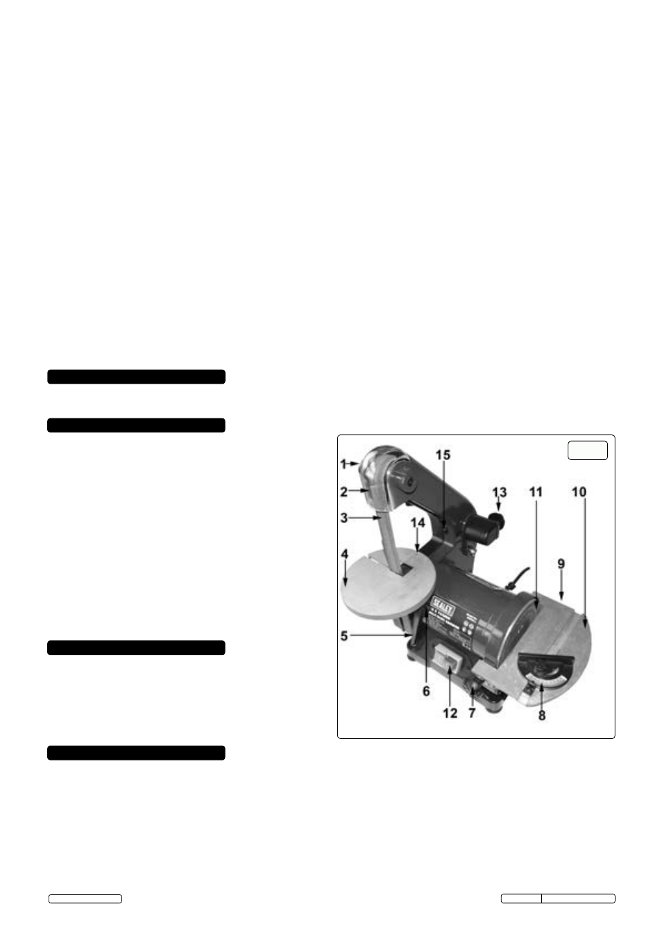
Fig.1, Assembly – Sealey SM750 User Manual
Page 2
NOTE: Remember that the disc and belt will still be moving for several seconds whilst slowing down, after switching off.
Familiar yourself with your working area and be alert for possible hazards, which you might not hear due to machine noise.
Inspect the work piece and remove all nails and screws before sanding.
Be aware that sparks may ignite the dust or fumes.
Switch off the belt and disc sander before making any adjustments and when the unit is not in use.
After finishing work and maintenance, disconnect the power lead from the mains supply.
In the event of an electrical or mechanical malfunction, immediately switch off the sander and do not use it further.
Always keep your work area clean.
Never use the power cable to carry the belt and disc sander. Keep the cable away from hot, sharp edges and moving parts.
WARNING! Always wear gloves and safety goggles and a dust mask as some coatings and wood dust may be harmful and toxic.
Always work in a well ventilated area. Whenever possible use the dust collection outlets provided on the machine.
Take care that the belt and disc sander cannot tip over or move while sanding long or heavy objects. If necessary, fasten the belt and
disc sander to a supporting surface.
Ensure that the sanding belt is running in the correct direction and ensure that the sanding disc or sanding belt is not damaged.
DO NOT allow children or untrained persons to operate the sander. Keep them away from the work area.
Ensure the sanding belt is correctly positioned and adjusted so that it cannot run off the pulleys.
DO NOT remove the safety guard whilst sander is in use.
Remove ill fitting clothing, ties and loose jewellery and tie back long hair. Keep hands and body clear of the worktable when operating
the sander.
DO NOT use the belt and disc sander near flammable liquids, gases or dust.
DO NOT disassemble the machine and do not try to repair it yourself. Have the unit repaired by a professional or contact your local
Sealey dealer. Always use original replacement parts.
DO NOT touch the sanding belt immediately after operation; it may be extremely hot and cause burns. The sanding belt is sharp-edged.
DO NOT use excessive force against the sanding belt or disc.
DO NOT operate the sander when you are tired, under the influence of alcohol, drugs or intoxicating medication.
DO NOT get the sander wet or use in damp or wet locations or areas where there is condensation.
DO NOT switch the sander on while the workpiece is in contact with the abrasive and DO NOT leave the sander running unattended
WARNING! The warnings, cautions and instructions in this manual cannot cover all possible conditions and situations that
may occur. It must be understood by the operator that common sense and caution are factors which cannot be built into
this product, but must be applied by the operator.
Bench mounting semi-portable belt and disc sander suitable for general woodworking applications. Powerful induction motor with smooth,
bearing-mounted drive pulleys gives quiet operation. Sanding disc table tilts to 45° and is supplied with mitre gauge for accurate angle sanding.
Sanding belt is positioned vertically.
1 Cover Clamp Knob
2 Clear Cover
3 Sanding Belt
4 Sanding Belt Table
5 Sanding Belt
6 Lever Locking Screw
7 2 x Table Clamp Knobs
8 Protractor Guide
9 2 X Dust Exhaust Outlets
10 Sanding Disc Table
11 Sanding Disc
12 On/Off (I/O) Switches
13 Belt Tracking Knob
14 Table Levelling Screw
15 3 x Cover Screws
2. INTRODUCTION
3. SPECIFICATION
4. CONTENTS (QUICK REF)
Model No: ................................................................................. SM750
Belt Size: ...........................................................................25 x 762mm
Belt Speed: ..........................................................................845mtr/min
Disc Size: ..................................................................................125mm
Disc Speed: ............................................................................ 2850rpm
Table Size: .......................................................................128 x 185mm
Table Tilt: ......................................................................................0-45°
Motor Power: ................................................................... 250W - 230V
Supply:.......................................................................................... 230V
Dust Extraction: ..................................................................2 x Ø45mm
Weight: .........................................................................................7.4kg
Replacement Sanding Belts: ..............................................................
Model No: .................................................................................Grade:
SM750B60G ............................................................. (Pack of 5) 60Grit
SM750B80G ............................................................. (Pack of 5) 80Grit
SM750B120G ......................................................... (Pack of 5) 120Grit
Replacement Sanding Discs: .............................................................
Model No: .................................................................................Grade:
SM750D80G ................................................................................80Grit
fig.1
5. ASSEMBLY
WARNING! Ensure that the sander is disconnected from the mains power supply before beginning assembly.
5.1.
Attaching the sanding disc dust extractor.
5.1.1. Attach the dust extractor plate (E) over the lower part of the sanding disc using the four screws provided as shown in fig.2.
5.2.
Attaching the sanding disc table.
5.2.1. on each inner mounting face of the sanding table adjustment scales there is a spigot which acts as a hinge point when adjusting the
angle of the table. See fig.3 (P). Hold the sanding table (T) in the position shown in fig.3 above, slide the spigots into the 'L' shaped
slots either side of the sanding disc until the table stops, then lift the table up until the spigots stop at point (S) on either side.
Retaining the table in this position, insert a clamping knob (K) through the curved slot in one of the sanding table adjustment scales
and screw it into the threaded hole provided in the flange around the disc. Tighten the knob to hold the table in position and then
screw the second knob 'K' into position on the other side of the table.
5.2.2. Place the adjustable, horizontal angle guide into the slot in the table when required (fig.1, Item 8) and adjust the angle as required and
clamp.
© Jack Sealey Limited
Original Language Version
SM750.V2 Issue No.1 - 08/06/15