Maintenance, Operating instructions – Sealey SM1311 User Manual
Page 4
WARNING! Ensure you read, understand and apply Section 1 safety instructions before use.
5.2
thicknessing
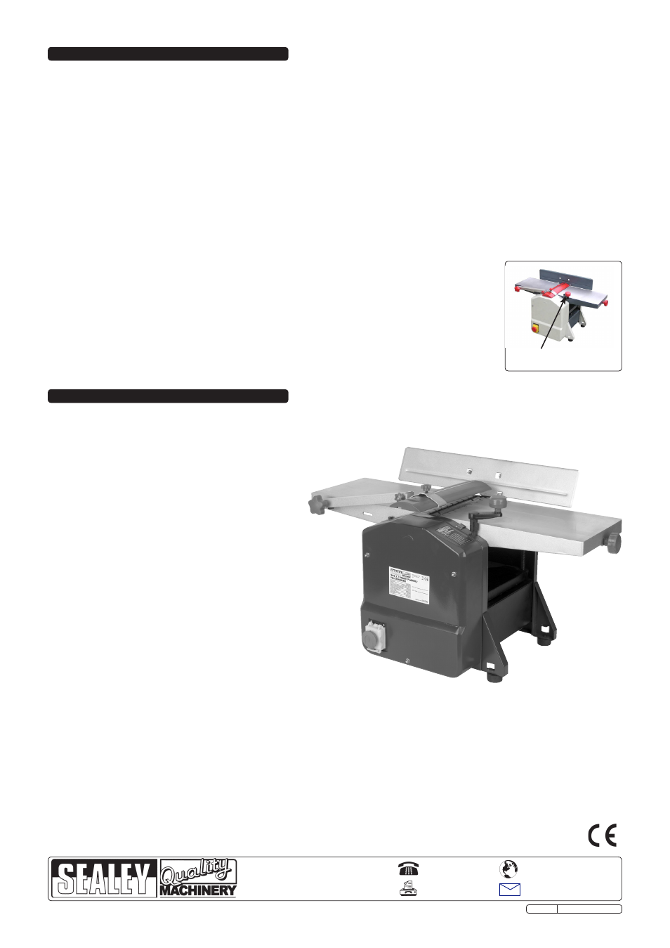
5.2.1 set the desired height by turning the handle (fig.B) using the graduated scale as a reference.
5.2.2 one complete turn of the handle is equal to 3mm as indicated on the scale next to the feed port.
It is better to use a cutting depth of between 0.5 and 1.5 mm (1/64”~1/16”) for best results. trying to
remove excessive amounts on a single pass will result in motor overload and dull the blades.
Note! When thicknessing it is recommended to keep the feed table clean and free of sap. Apply a small
amount of penetration spray and wipe over with a cloth.
WArnInG! Do not remove chips or dust from the table while the machine is running, always disconnect from
the mains supply before attempting any kind of maintenance. Do not attempt to thickness short pieces of wood.
fig.B
Height adjustment for
thicknesser table
WARNiNG! Prior to doing any maintenance work, always disconnect from the mains. Any protective guards which have been removed must
be mounted again after the maintenance work.
6.1
MAchiNE cARE
the sM1311 is designed with a low maintenance
requirement. the bearings are greased for life.
6.1.1 Grease threaded spindles for the height adjustment of
the thicknessing table.
6.1.2 the table surface should always be kept free of resin.
6.1.3 In order to prevent the motor from overheating,
regularly check that no dust has accumulated on
the ventilation apertures of the motor.
After a prolonged period of operation, users are
recommended to have the machine checked by
an authorised service agent.
6.2
tOOL cARE
the cutter head, clamping devices, blade supports and
blades used on the machine must be kept free from
resin build up as a clean tool improves the cutting
quality. this can be done by soaking the blade
supports and blades for 24 hours in paraffin, white
spirit or commercially available resin remover.
6.3
REPLAciNG BLADEs
WARNiNG! Disconnect from power before servicing!
6.3.1 unplug the planer from power source.
6.3.2 Loosen and remove four blade lock screws
securing blade and blade clamp.
6.3.3 Lift blade and blade clamp from cutterhead.
6.3.4 clean any sawdust and resin build up from cutterhead and blade clamp.
6.3.5 Place blade clamp against the replacement blade and replace in cutterhead.
6.3.6 secure blade and blade clamp using four blade lock screws. Do not over-tighten.
notE! check blade height and alignment.
6.3.7 to check blade alignment, set the table to the (0) position. use a straight edge i.e metal ruler or set square and position it across the
two tables. the blade should almost make contact with the ruler, check at either end of the blade and in the middle to ensure the blade
is level. Loosen the blade lock screws and adjust height accordingly using the blade adjustment grub screws.
6.3.8 repeat the procedure to replace the other blade.
6.3.9 Make sure all the blade lock screws are tight.
6. MAiNtENANcE
NOTE: It is our policy to continually improve products and as such we reserve the right to alter data, specifications and component parts without prior notice.
iMPORtANt: no liability is accepted for incorrect use of this product.
WARRANtY: Guarantee is 12 months from purchase date, proof of which will be required for any claim.
iNFORMAtiON: for a copy of our latest catalogue and promotions call us on 01284 757525 and leave your full name and address, including postcode.
01284 757500
01284 703534
sole Uk Distributor, sealey Group,
Kempson Way, suffolk Business Park
,
Bury st. Edmunds, suffolk,
IP32 7Ar
www.sealey.co.uk
Web
Original Language Version
sM1311 Issue: 2 - 23/11/09
5. OPERAtiNG iNstRUctiONs
WARNING! Ensure you read, understand and apply Section 1 safety instructions before use.
We recommend you check the alignment of cutting bladesbefore use. See section 6.3.7.
5.1
PLANiNG (Fig.A)
5.1.1 the cutting depth is set by handle (A). use the front table plate (B) in conjunction with the scale (c) for the cutting depth.
A cutting depth of between 0.5 and 1.5 mm (1/64”~1/16”) will produce the best results.
WARNING: The part of the blades not used, must to be covered by the blade guard.
Note! Attach a suitable dust extractor to the dust chute. This reduces the amount of airborne dust and health risks associated with
inhalation of particles.
5.1.2 take up a working position so that you are always on one side of the machine away from the area directly in front of or behind cutterhead.
5.1.3 Lift stoP cover and push the start button.
NOTE! The
STOP button is also the Emergency Stop button. Incase of an emergency hit the STOP button, it will lock into place to prevent the
start button being activated again. The stop button will require unclipping in order to gain access to the start button.
5.1.4 Place both hands on the workpiece. Do not hold the workpiece with your fingers anywhere near the blades.
NOTE! Only plane workpieces which rest firmly on the planer and can be safely guided.
5.1.5 Introduce the workpiece from the feed side. Gently guide the workpiece over the blades. Do not force the workpiece but allow the machine
to do the work.