Fig.6 fig.7 fig.8 – Sealey SM1302 User Manual
Page 4
4.4.
CLAMPING THE SCROLL SAW TO THE WORKBENCH. See Fig.5
If the scroll saw is to be used in several different places, it is recommended that you fasten it permanently to a mounting board that
can easily be clamped to a workbench or other supporting surface. the mounting board should be large enough to prevent the saw
from tipping while in use. Any good grade plywood or chipboard with a 3/4in. (19mm) thickness is recommended.
4.4.1. Mount the saw onto the board using the holes in the saw base as a template for the hole pattern. locate and mark the holes on the
board.
4.4.2. follow the last three steps in the previous section called Mounting the scroll saw onto a Workbench.
4.4.3. Make sure they are long enough to go through the holes in the saw base, the board on which the saw is mounted, and the washers
and nuts.
Note: It will be necessary to countersink the washers and nuts on the bottom side of mounting board.
4.5. ADJUSTMENTS
WARNING! to prevent accidental starting that could cause serious injury, turn off the saw and unplug it from the power source before
making any adjustments.
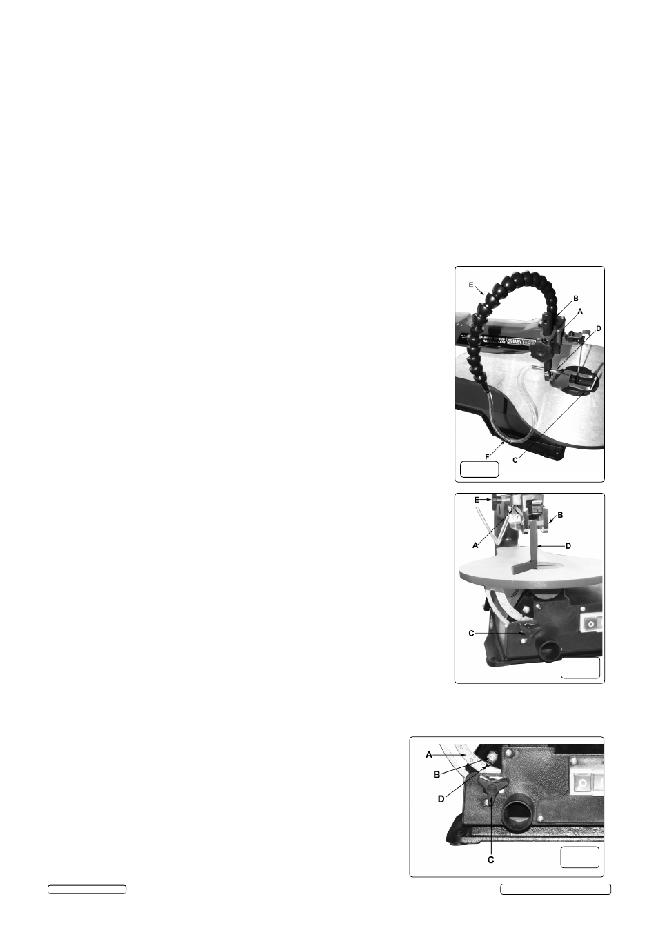
4.5.1. to prevent the workpiece from lifting, the drop foot should be adjusted so it just rests on
top of the workpiece. the drop foot should not be adjusted so tightly that the workpiece
drags. (see fig.6)
4.5.2. Always retighten the drop foot lock after each adjustment has been made.
4.5.3. loosen the drop foot lock.
4.5.4. lower or raise the drop foot to the desired position.
4.5.5. retighten the drop foot lock.
4.5.6. the two prongs at the front of the drop foot act as a blade guard to prevent the user
from accidentally touching the blade.
Fig.6
A. droP foot locK
d. sAWdust BloWer
B. PuMP MecHAnIsM
e. ArtIculAted Hose
c. droP foot
f. fleXIBle Hose
4.6.
SAWDUST
BLOWER.
See
Fig.6
WARNING! to avoid accidental starting which could result in serious injury, turn the saw off,
and unplug from the power source.
4.6.1. the sawdust blower is designed and preset to direct air to the most effective point on the
cutting line. screw the articulated hose into the threaded port on the pump mechanism then
connect the flexible hose to the nozzle.
4.6.2. Aternatively; the articulated hose can be used on its own if more suitable
4.6.3. Make sure the drop foot is properly adjusted to secure the workpiece and direct air at the
cutting surface.
4.7.
SQUARING THE SAW TABLE TO THE BLADE. See Fig.7
WARNING! to avoid accidental starting which could result in serious injury, turn the saw off
and unplug from the power source.
4.7.1. loosen the drop foot lock and move the drop foot rod all the way up.
4.7.2. retighten the drop foot lock.
4.7.3. loosen the table lock and tilt the saw table until it is approximately at right angles
to the blade.
4.7.4. Place a small square on the saw table next to blade and lock the table at 90° to block.
4.7.5. loosen the screw holding the scale indicator. see fig.8. Move the indicator to the 0°
mark and securely tighten the screw.
remember, the bevel scale is a convenient guide but should not be relied upon for precision.
Make practice cuts on scrap material to determine if your angle settings are correct.
Adjust the drop foot to the desired position and securely retighten the drop foot lock.
Fig.7
A. droP foot rod
d. sMAll sQuAre
B. droP foot
e. droP foot locK
c.
tABle
locK
4.8.
SETTING THE TABLE FOR HORIZONTAL OR BEVEL CUTTING See Fig.8
WARNING! to avoid accidental starting which could result in serious injury, turn the saw
off and unplug from the power source.
A bevel scale is located under the saw table as a convenient guide for setting the
approximate saw table angle for bevel cutting. When greater precision is required, make
practice cuts on scrap material and adjust the saw table as necessary for your
requirements.
Note: When cutting bevels, the drop foot should be tilted so it is parallel to the saw table and
rests flat on the workpiece. To tilt the drop foot, loosen the screw, tilt the drop foot to the
proper angle, then retighten the screw.
WARNING! to avoid accidental starting which could result in serious injury, turn the saw
off, and unplug from the power source.
Fig.8
A. BeVel scAle
c. tABle locK
B. screW
d. scAle IndIcAtor
Fig.6
Fig.7
Fig.8
sM1302 Issue: 3(sP) - 14/02/14
Original Language Version
© Jack sealey limited