Sealey SMS10 User Manual
Page 3
3. ASSEmBLY
WARNING! ENsuRE THAT THE sAW Is NOT CONNECTEd TO THE MAINs POWER BEfORE COMMENCING AssEMBLY.
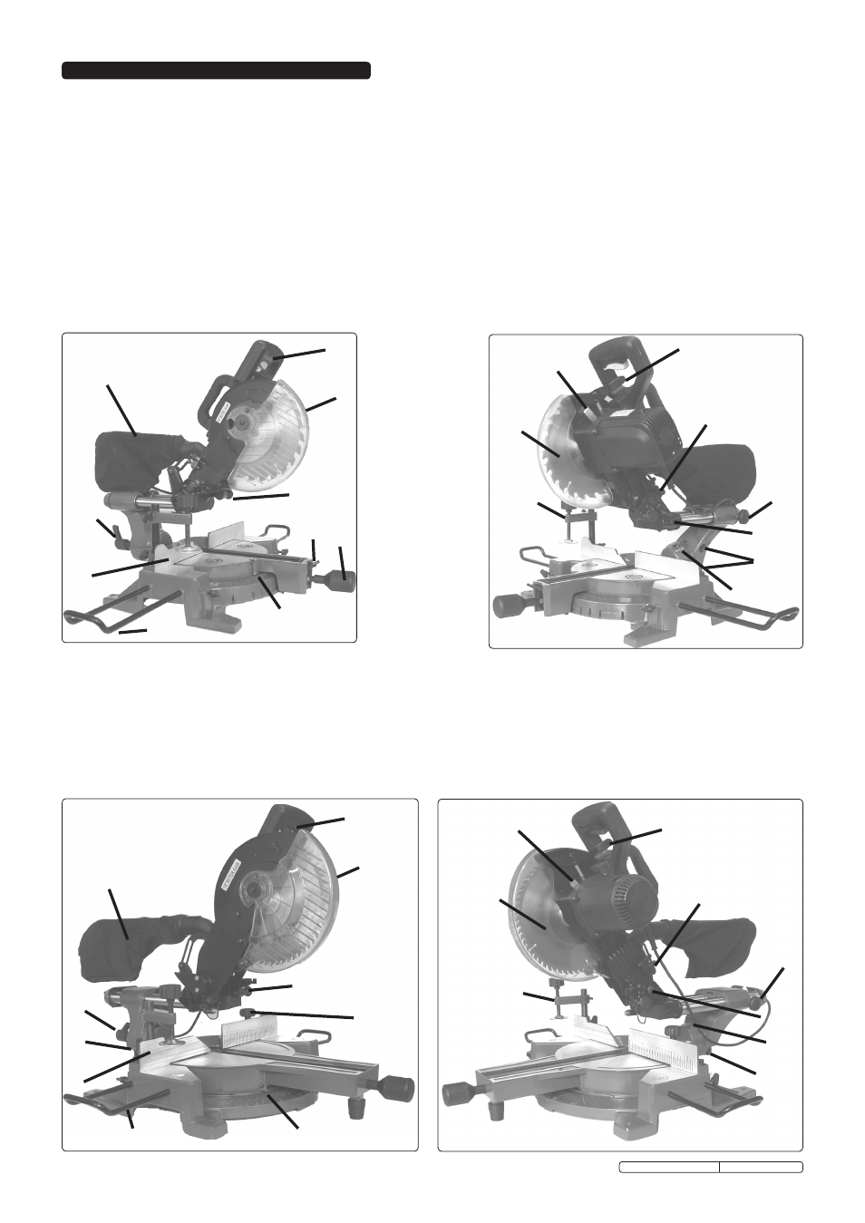
NOTE! fOR sMs8 REfER TO fIG.1, fOR sMs10 ANd sMs12 REfER TO fIG.2.
3.1
Screw the handle (6) into the work table.
3.2
Push workpiece supports (8) into the mounting holes at either end of the table extensions and secure with clamp screws.
3.3
Plug the clamping vice (16) into one of the two holes on the left or right of the base plate.
3.4
mOUNTING
The saw should be bolted to a sturdy workbench. Ensure that the supporting surface is strong enough to take the weight of the
saw and any workpiece. Position the saw in a suitable work area with enough clearance to allow room when working with large
workpieces.
Ensure that there is adequate lighting and that the saw blade can be clearly seen.
3.5
ExTRACTION
3.5.1 Connect the outlet to a suitable extraction system, or attach the dust bag (5).
WARNING! Wood dust can be harmful to health by inhalation and skin contact and concentrations of small dust particles in the air can
form an explosive mixture. Therefore, ensure that there is adequate ventilation and that the saw has the dust bag fitted or is attached
to a dust-extraction unit.
fig 1
SmS8
SmS8
1
2
3
4
5
6
7
8
9
10
11
12
13
16
18
17
14
15
19
19
1
ON/OFF Trigger
2
Guard Release Lever
3
Blade Guard
4
Adjustable Depth Stop
5
Dust Bag
6
Mitre Lock
7
Mitre Degree Pointer
8
Work Support
9
Fence
10
Laser Guide
11
Slide Lock
12
Saw Head Lock
13
Blade Lock
14
Bevel Lock
15
Bevel Degree Pointer
16
Clamping Vice
17
Blade
18
Mitre Lock Latch
19
Stop Screw
fig 2
SmS10, SmS12
SmS10, SmS12
1
2
3
4
5
6
7
8
9
10
11
12
13
16
17
14
15
19
19
Original Language Version
SMS8, SMS10, SMS12 issue: 2 - 22/03/10