Fig 1 fig 2, Introduction 3. specification, Preparation – Sealey GSA674K User Manual
Page 2
2. INTRODUCTION
3. SPECIFICATION
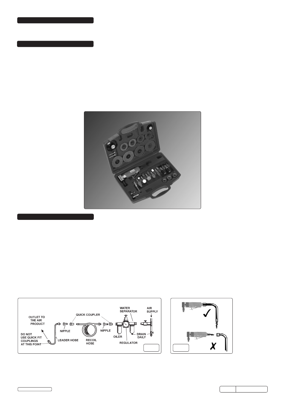
Suitable for die grinding, sanding or panel preparation. Includes our Generation Series 90° air angle die grinder (Model No: GSA674), which
features a safety trigger, contoured rubber handle and 360° rotating exhaust. Supplied in a storage case with a range of die grinding points, sanding
rolls and Ø50/75mm preparation pads. Replacement components readily available.
Model No: . . . . . . . . . . . . . . . . . . . . . . . . . . . . . . . . . . . . . . . . . . . . . . . . . . . . . . . . . . . . . . . . . . . . . . . GSA674K
Pad Size: . . . . . . . . . . . . . . . . . . . . . . . . . . . . . . . . . . . . . . . . . . . . . . . . . . . . . . . . . . . . . . . . . . Ø50mm, Ø75mm
Thread Size:. . . . . . . . . . . . . . . . . . . . . . . . . . . . . . . . . . . . . . . . . . . . . . . . . . . . . . . . . . . . . . . . . . . . . . . . ¼”UNC
Collet Size: . . . . . . . . . . . . . . . . . . . . . . . . . . . . . . . . . . . . . . . . . . . . . . . . . . . . . . . . . . . . . . . . . . . Ø3mm, Ø6mm
Free Speed; . . . . . . . . . . . . . . . . . . . . . . . . . . . . . . . . . . . . . . . . . . . . . . . . . . . . . . . . . . . . . . . . . . . . . . 20000rpm
Air Consumption: . . . . . . . . . . . . . . . . . . . . . . . . . . . . . . . . . . . . . . . . . . . . . . . . . . . . . . . . . . . . . . . . . . . . . . 4cfm
Operating Pressure: . . . . . . . . . . . . . . . . . . . . . . . . . . . . . . . . . . . . . . . . . . . . . . . . . . . . . . . . . . . . . . . . . . . . 90psi
Air Inlet Size: . . . . . . . . . . . . . . . . . . . . . . . . . . . . . . . . . . . . . . . . . . . . . . . . . . . . . . . . . . . . . . . . . . . . . . . ¼” BSP
Weight (tool only): . . . . . . . . . . . . . . . . . . . . . . . . . . . . . . . . . . . . . . . . . . . . . . . . . . . . . . . . . . . . . . . . . . . . 0.54kg
Noise Pressure/Power:. . . . . . . . . . . . . . . . . . . . . . . . . . . . . . . . . . . . . . . . . . . . . . . . . . . . . . . . . . . . . . 95/84dBA
Vibration/Uncertainty: . . . . . . . . . . . . . . . . . . . . . . . . . . . . . . . . . . . . . . . . . . . . . . . . . . . . . . . . . . . . 1.44/0.72m/s²
4.1.
Air Supply
4.1.1. Ensure grinder air valve (or trigger) is in "off" position before connecting to the air supply.
4.1.2. Use an air pressure of 90psi, and an air flow according to specification.
4.1.3.
WARNING! Ensure the air supply is clean and does not exceed 90 psi while operating the grinder. Too high an air pressure and
unclean air will shorten the product life due to excessive wear, and may be dangerous causing damage and/or personal ury.
4.1.4. Drain the air tank daily. Water in the air line will damage the grinder.
4.1.5. Clean air inlet filter weekly. Recommended hook-up procedure is shown in fig 1.
4.1.6. Line pressure should be increased to compensate for unusually long air hoses (over 8 metres). The minimum hose diameter should be
1/4” I.D. and fittings must have the same inside dimensions.
4.1.7. Keep hose away from heat, oil and sharp edges. Check hose for wear, and make certain that all connections are secure.
4.2. Couplings.
Vibration may cause failure if a quick change coupling is connected directly to the die grinder.
To overcome this, connect a leader hose to the grinder. A quick change coupling may then be used to connect the leader hose to the air
line recoil hose. See fig 1 & 2.
4. PREPARATION
fig 1
fig 2
GSA674K Issue: 1 - 05/12/14
Original Language Version
© Jack Sealey Limited