Fig.1 fig.2, Preparing tool for use 4. operating instructions, Introduction & specification – Sealey SA650 User Manual
Page 2
Original Language Version
SA650.V3 Issue: 3(SP) - 20/11/13
3.1.
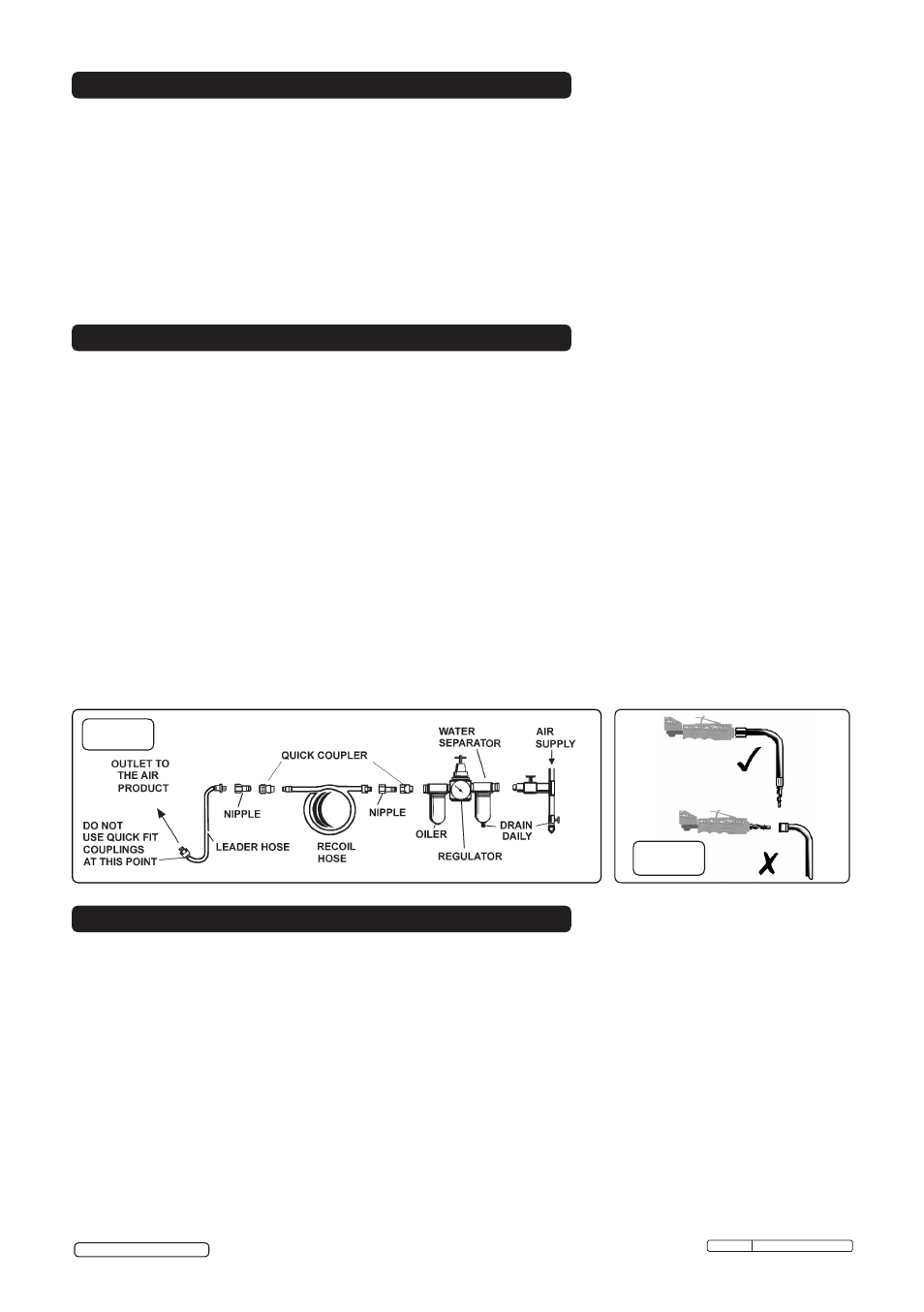
Air Supply.
Recommended hook-up procedure is shown in fig 1.
3.1.1. Ensure tool air control valve (or trigger) is in "Off" position before connecting to the air supply.
3.1.2. You will require an air pressure of 90psi, and an air flow according to specification.
3.1.3.
WARNING! Ensure the air supply is clean and does not exceed 90psi while operating the tool. Too
high an air pressure and unclean air will shorten the product life due to excessive wear, and may be
dangerous causing damage and/or personal injury.
3.1.4. Drain the air tank daily. Water in the air line will damage the tool.
3.1.5. Clean air inlet filter weekly.
3.1.6. Line pressure should be increased to compensate for unusually long air hoses (over 8 metres). The
minimum hose diameter should be 1/4” I.D. and fittings must have the same inside dimensions.
3.1.7. Keep hose away from heat, oil and sharp edges. Check hose for wear, and make certain
that all connections are secure.
3.2. Couplings.
Vibration may cause failure if a quick change coupling is connected directly to the tool.
To overcome this, connect a leader hose to the tool. A quick change coupling may then be used to
connect the leader hose to the air line recoil hose (see figs.1 & 2).
3.
PREPARING TOOL FOR USE
4. OPERATING INSTRUCTIONS
fig.1
fig.2
2.
INTRODUCTION & SPECIFICATION
Disc size: . . . . . . . . . . . . . . . . . . . . . .Ø75mm
Free speed: . . . . . . . . . . . . . . . . . 20,000rpm
Air consumption:. . . . . . . . . . . . . . . . . . . 4cfm
Operating pressure: . . . . . . . . . . . . . . . .90psi
Air inlet size:. . . . . . . . . . . . . . . . . . . 1/4”BSP
Weight: . . . . . . . . . . . . . . . . . . . . . . . . . 0.8kg
Noise Power: . . . . . . . . . . . . . . . . . 103dB(A)
Noise Pressure: . . . . . . . . . . . . . . . . 92dB(A)
Measured Vibration Emission Value: 6.65m/s²
Uncertainty Value: . . . . . . . . . . . . . . 1.15m/s²
Spare Disc Part No: . . . . . PTC/3C (single)
. . . . . . . . . . . . . . . . . . PTC/3C5 (Pack of 5)
Composite cover moulded around lightweight aluminium alloy housing reduces effects of chill on operator’s
hands and provides added control. Air motor with quality bearings for smooth and powerful operation. Exhaust
outlet adjusts 360° keeping air flow away from operator. Fitted with metal safety guard and safety trigger to
prevent inadvertent operation. Suitable for the professional workshop.
4.1.
FITTING CUTTING DISC.
WARNING! Disconnect from the air supply before changing disc.
4.1.1. Use hex key to remove hex screw and flange.
4.1.2. Place the cutting disc onto the spindle.
4.1.3. Replace the flange and secure with hex screw, but do not over tighten.
Check that replacement disc is not damaged, (cracks, deformations or splinters etc).
Also check the mounting flange to ensure it is not deformed, burred or notched.
A damaged flange must not be used as it may cause irregular pressure on the disc which may cause it
to break.
DO NOT tamper with a disc in order to adapt it to a different size holder.
© Jack Sealey Limited