Front components, Chapter 2, System components – Lanner LEC-2110 User Manual
Page 8
8
System Components
Chapter 2
Embedded and Industrial Computing
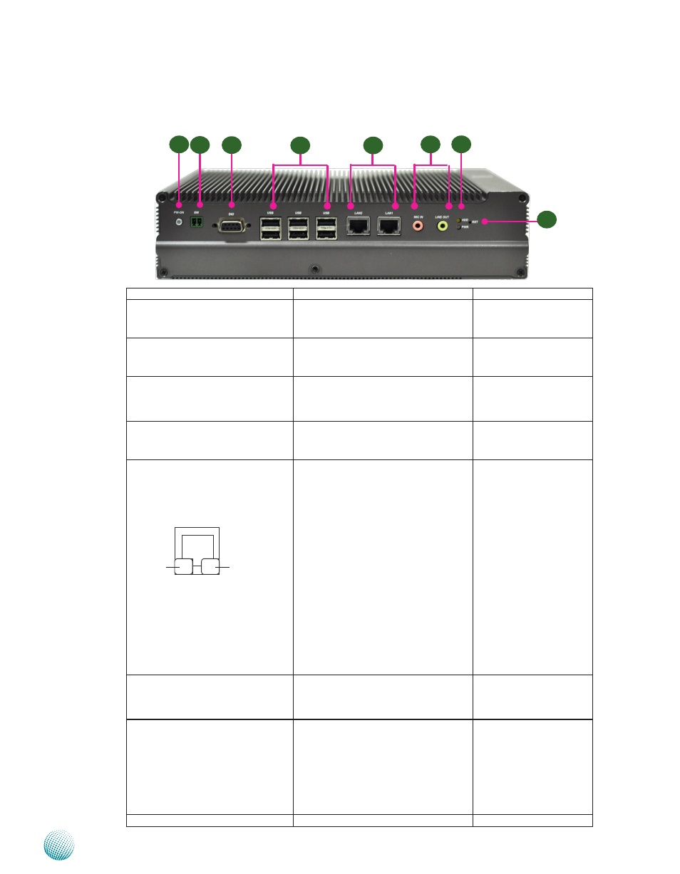
Front Components
Component
Description
Pin Definition Reference
F1 Power Button with dual LED
ATX Power-on button with LEDs:
Standby mode in Red; Power-on mode
in Green
PSBTN1 on page 15
F2 Power-on Switch
A power-on switch through the
Phoenix contact for distant power-on/
off control
PSW1 on page 15
F3 DIO Port
A Digital Input/Output port supports 4
input and 4 output connections. They
are provided by Fintek F81865 super
I/O
DGIO on page 14
F4 Six USB 2.0 Ports
An USB type A connector. In addition to
this connector, an internal pin header is
provided..
Dual USB Port Connectors
on Page 15
F5 Two 10/100/1000Mbps LAN ports Two RJ-45 (network) jacks with LED
indicators as described below. The LAN
ports are provided by Realtek 8111E.
They both support Wake-on-LAN/
Remote-wake-up.
LINK/ACT (Yellow)
On/Flashing: The port is linking
•
and active in data transmission.
Off: The port is not linking.
•
SPEED (Green/Amber)
Amber: The connection speed is
•
1000Mbps.
Green: The connection speed is
•
100Mbps
Off: .The connection speed is
•
10Mbps.
LANB1, LANB2 on page
14
F6 MIC IN/ LINE OUT
Connect the audio devices to these
ports. The Microphone and line out
port are provided by Realtek ALC
ALC888S
MIC1on page 15
F7 HDD (Yellow) and
Power LED (Green)
HDD
Blinking: data access activities
•
Off: no data access activities
•
Power
On: The computer is on.
•
Off: The computer is off .
•
LED3 on page 17
F8 Reset
Reset switch
F1
F2
F4
F5
F7
F8
F3
F6
Speed
Link/Active