Chapter 3, Board layout – Lanner LEC-2110 User Manual
Page 15
15
Board Layout
Chapter 3
Embedded and Industrial Computing
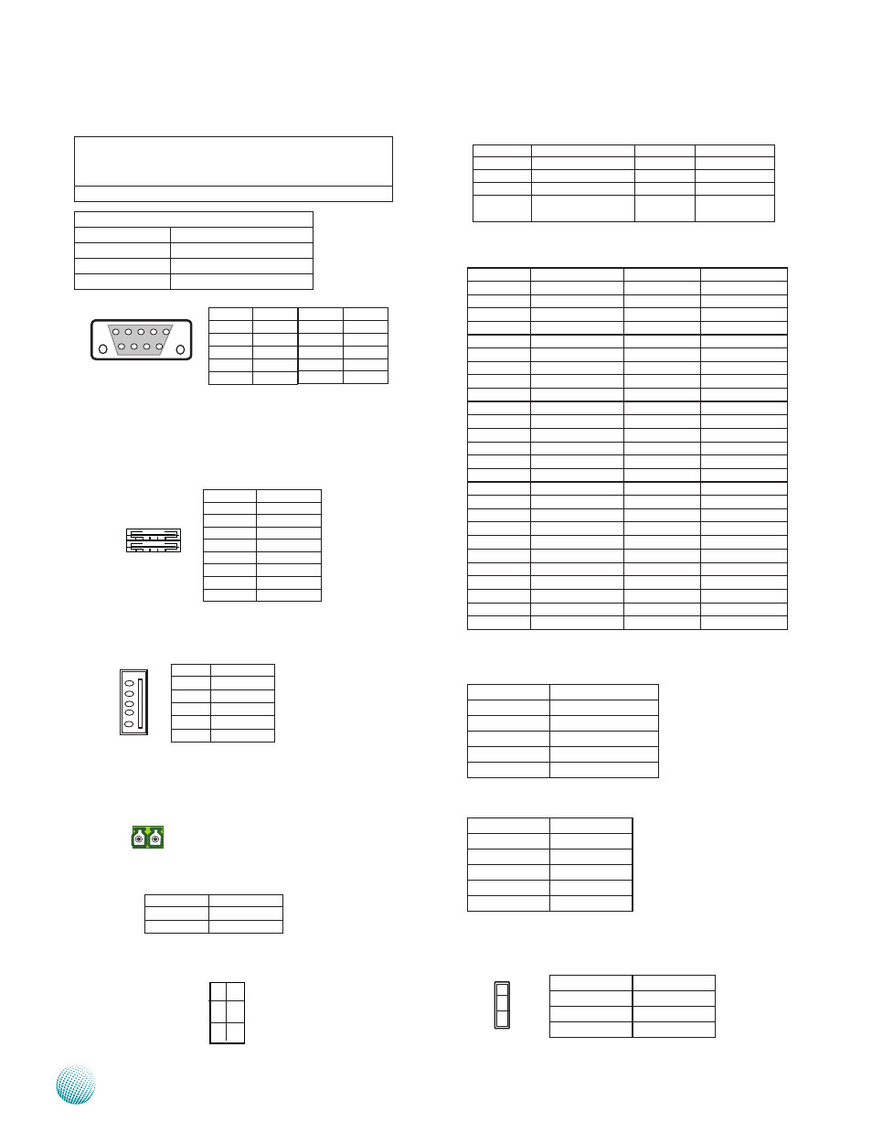
Mini PCI Express Connector (MPCIE1):
Pin No.
Description
Pin No.
Description
1
WAKE#
2
+3.3V
3
RSV1
4
Ground
5
RSV2
6
+1.5V
7
CLKREQ#
8
UIM_PWR
9
Ground
10
UIM_DATA
11
REFCLK-
12
UIM_CLK
13
REFCLK+
14
UIM_RESET
15
GND3
16
UIM_VPP
17
RSV3
18
Ground
19
RSV4
20
W_DISABLE#
21
GND5
22
PERST#
23
PERn0
24
+3.3V
25
PERp0
26
Ground
27
Ground
28
+1.5V
29
Ground
30
SMB_SLK
31
PETn0
32
SMB_DATA
33
PETp0
34
Ground
35
Ground
36
USB_D-
37
Ground
38
USB_D+
39
+3.3V
40
Ground
41
+3.3V
42
LED_WWAN#
43
Ground
44
LED_WLAN#
45
RSV9
46
LED_WPAN#
47
RSV10
48
+1.5V
49
RSV11
50
Ground
51
RSV12
52
+3.3V
Line-out Connector through 5-pin jack (LNO1)
Pin No.
Description
1
CO_GND
2
LINOUT-L
3
CO_GND
4
LINOUT-JDET
5
LINOUT- R
Microphone Connector through 5-pin jack (MIC1:)
Pin No.
Description
1
CO_GND
2
MIC_INL
3
CO_GND
4
MIC-JDET
5
MIC_INR
Line-in (LIN1, reserved for future customization)
Pin No.
Description
1
LININ-L
2
CO_GND
3
LININ-R
TTL Level is +5V; Maximum input current for each port
is 10mA; Maximum output current for each port is
100uA
The default value is 0
DIO Address
Address
Description
0x2eH
SUPERIO_INDEX
Digital Input
GPIO4, GPIO50~GPIO52
Digital Output GPIO0~GPIO3
Dual USB Port Connector #0 and #1 (USB1):
Dual USB Port Connector #2 and #3 (USB2):
Dual USB Port connector #4 and #5 (USB3):
USB 2.0 Pin Header (USBG1, USB#6):
Power on Switch through the Phoenix Contact
(PSW1):
Power-on Button with dual color (PSBTN1)
PIN NO.
DESCRIPTION
1
PWR_BTN_N
2
GND
1 2 3 4
5 6 7 8
Pin No.
Pin Name
1
+5V
2
USBD0-
3
USBD0+
4
GND
5
+5V
6
USBD1-
7
USBD1+
8
GND
Pin No. Pin Name
1
+5V
2
USBD6-
3
USBD6+
4
GND
5
NC
Pin No.
Pin Name
1
Input0
2
Input1
3
Input2
4
Input3
5
GND
Pin No.
Pin Name
6
Output0
7
Output1
8
Output2
9
Output3
9 8 7 6
5 4 3 2 1
1
L1
2
3
L2
4
PIN NO.
DESCRIPTION
PIN NO.
DESCRIPTION
PAD1
Ground
PAD2
Ground
1
Ground
3
BUTTON-
2
Ground
4
BUTTON-
L1
PWR_LED+ /
STB_LED-
L2
PWR_LED- /
STB_LED+
1 2
Note: The orientation of CN2 illus-
trated here is opposite of the one on
the front panel.
5
4
3
2
1
1
2
3