Jumper settings, Chapter 3, Board layout – Lanner LEC-2110 User Manual
Page 13
13
Board Layout
Chapter 3
Embedded and Industrial Computing
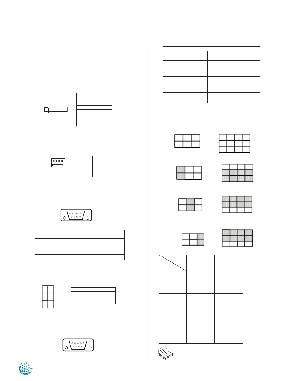
SC2T1, SC2T2: Select COM2 Protocol Setting
RS-232
RS-422
RS-485
Switch
Protocol
SC2T1
SC2T2
RS-232
(Default)
1-2
1-5
2-6
3-7
4-8
RS-422
3-4
5-9
6-10
7-11
8-12
RS-485
5-6
5-9
6-10
7-11
8-12
Note: When using RS-422/RS-485 in COM2, you
must enable the “Serial Port2/3 RS485 driver”
option first in the BIOS menu.
Jumper Settings
Serial-ATA Connector (SATA1): It is for connecting a 2.5’’
harddisk to be served as your system’s storage. It can
support SATA II which features Data transfer rates up to
3.0 Gb/s (300 MB/s).
4-pin Serial-ATA Power Connector (PS4S1): It is for
connecting the SATA power cord.
RS-232 Serial Port(COM1): It is a RS-232 port through the
D-SUB9 connector.
Select COM1/COM2 Pin 9 function: Pin 9 of RS-232
port (PCOM1/PCOM2) can be altered according to the
following definition:
RS-232/422/485 Serial Port (COM2): It is a RS-
232/422/485 port through the D-SUB9 connector.
6 7 8 9
1 2 3 4 5
Pin No.
Pin Name
Pin No.
Pin Name
1
DCD
6
DSR
2
RXD
7
RTS
3
TXD
8
CTS
4
DTR
9
RI
5
GND
Pin No.
Function
1
GND
2
TX+
3
TX-
4
GND
5
RX-
6
RX+
7
GND
LEB-2110A
Pin No.
Function
1
+12V
2
GND
3
GND
4
+5V
1 2 3 4 5 6 7
1 2 3 4
Pin No.
Pin Name
RS-232
RS-422
RS-485
1
DCD
TxD-
Data-
2
RXD
TxD+
Data+
3
TXD
RxD+
4
DTR
RxD-
5
GND
6
DSR
7
RTS
8
CTS
9
RI
6 7 8 9
1 2 3 4 5
9
5
1
12
8
4
SC2T2
SC2T1
2
1
6
5
1
3
5
2
4
6
Pin No.
Function
1-2 (Default)
Ring In
3-4
+5V
5-6
+12V