Chapter 3, Board layout – Lanner LEC-2110 User Manual
Page 14
14
Board Layout
Chapter 3
Embedded and Industrial Computing
SW2: Select COM2 and COM3 Termination in RS-
485 This switch is used to enable or disable the signal
termination for COM2 and COM3. We strongly recommend
that you disable termination when the port is configured
as RS-232 and enable it when the port is configured as RS-
485/RS-422.
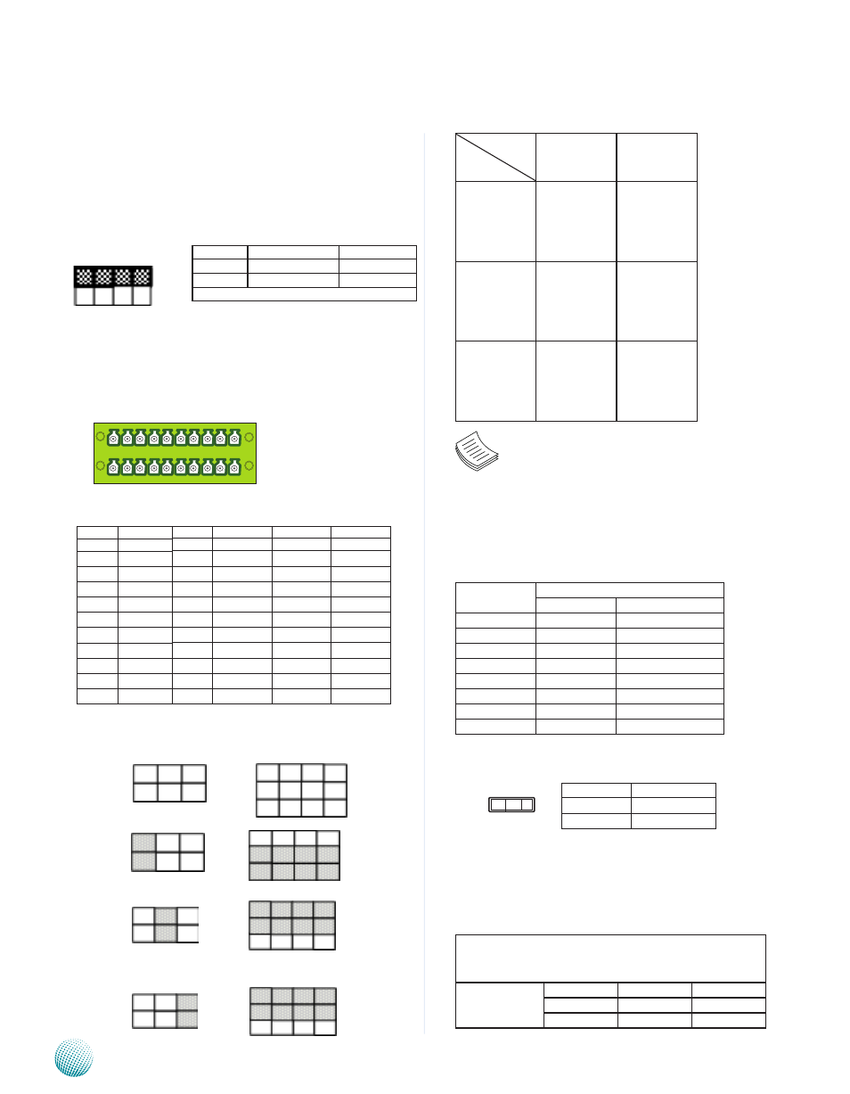
RS-232/422/485 Serial Port (COM3~COM6, CN2): It has
4 serial ports through terminal block connector. Note that
only COM3 can select among RS232/422/485.
SC3T1 and SC3T2: Select COM3 Protocol Setting
RS-232
RS-422
RS-485
Switch
Protocol
SC3T1
SC3T2
RS-232
(Default)
1-2
1-5
2-6
3-7
4-8
RS-422
3-4
5-9
6-10
7-11
8-12
RS-485
5-6
5-9
6-10
7-11
8-12
Note: When using RS-422/RS-485 in COM2, you
must enable the “Serial Port2/3 RS485 driver”
option first in the BIOS menu.
LAN1/LAN2 Ports (LANB1/LANB2): The LAN ports are
provided by RTL8111E-VB-CG Ethernet controller whose
interface complies with PCI-e 1.1 (2.5 Ghz) and IEEE
802.3az Draft 3.0 (EEE). It has advanced management
features including Wake-on-LAN and remote wake-up .
Pin No.
Description
Fast Ethernet Gigabit Ethernet
1
TX+
MD0+
2
TX-
MD0-
3
RX+
MD1+
4
T45
MD2+
5
T45
MD2-
6
RX-
MD1-
7
T78
MD3+
8
T78
MD3-
Clear CMOS jumper (CMOS1): It is for clearing the CMOS
memory.
Digital I/O (DGIO1)
Digital IN/OUT(DIO1) Connector: The 8 pins of General
Purpose Input/Output (GPIO) support input and output
operations through the DB-9 female connector.
TTL Level is +5V; Maximum input current for each port
is 10mA; Maximum output current for each port is
100uA
Input/Output Voltage
Logic
Register
0~2V
Low
0
2~5V
High
1
Pin No.
Pin Name
1-2
Normal (Default)
2-3
Clear CMOS
Pin No. Pin Name
RS-232
1
RTS5#
2
RxD5
3
TxD5
4
CTS5#
5
CGND
6
RTS6#
7
RxD6
8
TxD6
9
CTS6#
10
DGND
Pin No. Pin Name
RS-232
RS-422
RS-485
11
RTS3#
TX-
DATA-
12
RxD3
TX+
DATA+
13
TxD3
RX+
14
CTS3#
RX-
15
EGND
16
RTS4#
17
RxD4
18
TxD4
19
CTS4#
20
FGND
SW2
ON
OFF
COM Port
Pin Number
Termination
COM2
Selector 1, 2 on/off
Enable/Disable
COM3
Selector 3,4 on/off
Enable/Disable
The default setting is “Disable”
SC2T1
2
1
6
5
9
5
1
12
8
4
SC2T2
1 2 3
10 9 8 7 6 5 4 3 2 1
20 19 18 17 16 15 14 13 12 11
COM6 COM5
COM4 COM3
Note: The orientation
of CN2 illustrated here
is opposite of the one
on the front panel.